Search filter
Filter
Reset- Installation drawing (779)
- Product data sheet (611)
- Installation instructions (239)
- Tender texts (223)
- 3D model (148)
- Product scale drawing (142)
- Certificate (75)
- Declaration of conformity (57)
- Declarations of performance (54)
- Cable plan (45)
- Wiring diagram (39)
- Environmental declaration (36)
- User manual (25)
- Supplementary sheet (16)
- Flyer/folder (16)
- Product brochure (15)
- T&C / Data Protection (8)
- Inspection certificate (7)
- Type examination certificate (5)
- Product shot (3)
- Software (3)
- Safety analysis (2)
- Supplier information (1)
2549 results found

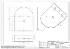
Base for floor mounting for hold-open magnet
(DWG | 115 KB)
Wall bracket ceiling-mounted detector
(PDF | 69 KB)
Wall bracket ceiling-mounted detector
(DWG | 70 KB)
GC 152 Ceiling-mounted smoke detector, GC 153 Thermal detector
(DWG | 293 KB)
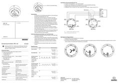
140403_00_Deckenrauchmelder_ceiling smoke detector_ORS_142.pdf
LED zur Zustandsanzeige Anschluß an Sturzrauchschalter GC 151 XX Jumper J2 (rot) abziehen (= mit Deckenmelder). XX Jumper J3 zur Messkammer hin setzen (Pin 2-3, = mit Leitungsüberwachung). XX Magnethalter im Sockel des letzten ORS 142 befestigen. XX Kabeltyp J-Y(ST)Y, 2x2x0,6 mm2 oder 2x2x0,8 mm2 verwenden. Länge maximal 15 m. Klemmdose ORS 142 Verwendung Der ORS 142 ist ein Deckenrauchmelder zur Verwendung in der GEZE Feststellanlage FA GC 150. Rauchmelder erkennen Rauch. Sie arbeiten nach dem Streulichtprinzip. Ein Lichtsender und ein Lichtempfänger sind in der Messkammer so angeordnet, dass normalerweise kein Licht auf den Empfänger fällt. Befinden sich Schwebeteilchen (Rauch) in der Messkammer, so streuen diese einen Teil des Lichtes auf den Empfänger, der dieses in ein elektrisches Signal umsetzt. Der potentialfreie Alarmausgang (Relais) des Rauchmelders öffnet. Ein Rauchmelder erkennt also nicht nur Rauch, sondern auch alle anderen Schwebeteilchen und reagiert empfindlich auf Verschmutzung. Der ORS 142 enthält zusätzlich einen Temperaturfühler, der bei 70°C anspricht. Bei einer Temperatur größer als 70°C öffnet ebenfalls der Alarmausgang. DE Beiblatt DE Rauchmelder 140403-01 Deckenrauchmelder ORS 142 EN 14637 Dokument FA GC 150 - Anleitung zur Montage, Inbetriebnahme, Bedienung und Wartung beachten, siehe www. geze.com - Mat. Nr. 141511. Schutz des Deckenrauchmelders vor Verschmutzung àà Die Staubschutzkappe des Rauchmelders erst bei der Inbetriebnahme entfernen. àà Nach Einbau des Rauchmelders und Entfernung des Staubschutzes darauf achten, dass kein Staub in die Messkammer gelangt. Dies führt zu einer erhöhten Verschmutzung und kann die Lebensdauer des Rauchmelders erheblich verkürzen. àà Die Messkammer des Rauchmelders darf nicht geöffnet werden. Deckenrauchmelder ORS 142 mit àà Rauchmelder ORS 142 àà Sockel ORS 143 A àà … x Magnethalter Farbe Abmessungen (mit Sockel, DxH) Funktionsprinzip àà Raucherkennung Mat. Nr. 091069 weiß, RAL 9010 80 mm x 66 mm àà Temperaturfühler Streulicht, Alarmschwellennachführung, selbstrückstellend 70°C ±5 Eingangsspannung 24 V DC Eingangsstrom Einbaulage Schutzart Umgebungstemperatur Alarmausgang maximal 22 mA Deckenmontage IP42 -20°C bis 60°C potentialfreier Relaisausgang, Öffner maximal 24 V DC / max. … A Magnethalter schaltet im letzten Deckenrauchmelder 2x 43 k Ω zu. Meldertest Alarmauslösung mit Prüfgas Befestigen des Magnethalters XX Magnethalter in die Sockelklemme … einsetzen. XX Schraube mittelstark anziehen. XX Der Deckenrauchmelder ORS 142 kann in Bestandsanlagen verwendet werden. Hierfür den Raucherkennungsteil auf dem vorhandenen Sockel, mit bestehender Verdrahtung, verwenden. Signalisierung LED Spannungslos aus Normalbetrieb GN Technische Daten Kit Deckenrauchmelder ORS 142 mit Mat. Nr. 141715 àà … x Rauchmelder ORS 142 àà … x Sockel ORS 143 A àà … x Magnethalter AS Deckenmelder (additional sensor) GND Bezugspotential (ground) Verschmutzung YEYE (Warnung) GN Der Deckenrauch- GN melder sollte ausgetauscht werden. Verschmutzungs- YEYE grenze erreicht GNGN Der Deckenrauchmelder muss ausgetauscht werden. Fehler YE Der Deckenrauchmelder muss ausgetauscht werden. Alarm RD Relaisausgang ASout … ASin … ASout … ASin … ASout … ASin … ASout … ASin … ASout … ASin … ASout … ASin … Germany GEZE GmbH Niederlassung Süd-West Tel. +49 (0) 7152 203 594 E-Mail: leonberg.de@geze.com GEZE GmbH Niederlassung Süd-Ost Tel. +49 (0) 7152 203 6440 E-Mail: muenchen.de@geze.com GEZE GmbH Niederlassung Ost Tel. +49 (0) 7152 203 6840 E-Mail: berlin.de@geze.com GEZE GmbH Niederlassung Mitte/Luxemburg Tel. +49 (0) 7152 203 6888 E-Mail: frankfurt.de@geze.com GEZE GmbH Niederlassung West Tel. +49 (0) 7152 203 6770 E-Mail: duesseldorf.de@geze.com GEZE GmbH Niederlassung Nord Tel. +49 (0) 7152 203 6600 E-Mail: hamburg.de@geze.com GEZE Service GmbH Tel. +49 (0) 1802 923392 E-Mail: service-info.de@geze.com Austria GEZE Austria E-Mail: austria.at@geze.com www.geze.at Baltic States GEZE GmbH Baltic States office E-Mail: office-latvia@geze.com www.geze.com Benelux GEZE Benelux B.V. E-Mail: benelux.nl@geze.com www.geze.be www.geze.nl Bulgaria GEZE Bulgaria - Trade E-Mail: office-bulgaria@geze.com www.geze.bg GEZE GmbH Reinhold-Vöster-Straße 21–29 71229 Leonberg Germany China GEZE Industries (Tianjin) Co., Ltd. E-Mail: chinasales@geze.com.cn www.geze.com.cn Iberia GEZE Iberia S.R.L. E-Mail: info@geze.es www.geze.es Russia OOO GEZE RUS E-Mail: office-russia@geze.com www.geze.ru Switzerland GEZE Schweiz AG E-Mail: schweiz.ch@geze.com www.geze.ch GEZE Industries (Tianjin) Co., Ltd. Branch Office Shanghai E-Mail: chinasales@geze.com.cn www.geze.com.cn India GEZE India Private Ltd. E-Mail: office-india@geze.com www.geze.in Scandinavia – Sweden GEZE Scandinavia AB E-Mail: sverige.se@geze.com www.geze.se Turkey GEZE Kapı ve Pencere Sistemleri E-Mail: office-turkey@geze.com www.geze.com GEZE Industries (Tianjin) Co., Ltd. Branch Office Guangzhou E-Mail: chinasales@geze.com.cn www.geze.com.cn Italy GEZE Italia S.r.l E-Mail: italia.it@geze.com www.geze.it Scandinavia – Norway GEZE Scandinavia AB avd. Norge E-Mail: norge.se@geze.com www.geze.no Ukraine LLC GEZE Ukraine E-Mail: office-ukraine@geze.com www.geze.ua GEZE Industries (Tianjin) Co., Ltd. Branch Office Beijing E-Mail: chinasales@geze.com.cn www.geze.com.cn GEZE Engineering Roma S.r.l E-Mail: roma@geze.biz www.geze.it Scandinavia – Denmark GEZE Danmark E-Mail: danmark.se@geze.com www.geze.dk United Arab Emirates/GCC GEZE Middle East E-Mail: gezeme@geze.com www.geze.ae Singapore GEZE (Asia Pacific) Pte, Ltd. E-Mail: gezesea@geze.com.sg www.geze.com United Kingdom GEZE UK Ltd. E-Mail: info.uk@geze.com www.geze.com France GEZE France S.A.R.L. E-Mail: france.fr@geze.com www.geze.fr Hungary GEZE Hungary Kft. E-Mail: office-hungary@geze.com www.geze.hu Tel.: 0049 7152 203 … Fax: 0049 7152 203 310 www.geze.com Poland GEZE Polska Sp.z o.o. E-Mail: geze.pl@geze.com www.geze.pl Romania GEZE Romania S.R.L. E-Mail: office-romania@geze.com www.geze.ro South Africa GEZE South Africa (Pty) Ltd. E-Mail: info@gezesa.co.za www.geze.co.za LED for status indication Connection to the lintel smoke switch GC 151 XX Remove the red jumper J2 (= with ceiling detector). XX Set jumper J3 to the measuring chamber (Pin 2-3, = with line monitoring). XX Fasten the magnet holder in the socket of the last ORS 142. XX Use cabel type J-Y(ST)Y, 2x2x0,6 mm2 or 2x2x0,8 mm2. Maximum length less than 15 m. connection box Use ORS 142 EN Supplement EN Ceiling smoke detector 140403-01 Ceiling smoke detector ORS 142 EN 14637 Document FA GC 150 - Observe instructions for installation, commissioning, operation and maintenance, see www.geze. com - Mat. No. 141512. The ORS 142 is a ceiling smoke detector for use in the GEZE hold-open device FA GC 150. Smoke detectors recognise smoke. They operate on the principle of diffused light. A light emitter and a light receiver are arranged in the measuring chamber in such a way that normally no light falls on the receiver. If there are suspended particles (smoke) in the measuring chamber, this scatters a portion of the light on the receiver, which converts it into an electrical signal. The potential-free alarm output (relay) opens the smoke detector. A smoke detector recognises not only smoke, but also all other suspended particles and is sensitive to pollution. The ORS 142 also includes a temperature sensor, which responds at 70°C. A temperature higher than 70°C also opens the alarm output. Protection of the smoke detector against dirt accumulation àà Remove the dust cover of the smoke detector only at the time of the initial operation. àà After the installation of the smoke detector and removal of the dust cover, ensure that dust does not enter the measuring chamber. Otherwise it may result in increased dust accumulation that can significantly shorten the service life of the smoke detector. àà The measuring chamber of the smoke detector should not be opened. àà Temperature sensor Input voltage Input current Installation position Protection type Ambient temperature Alarm output Magnet holder Detector test Mat. No. 141715 Mat. No. 091069 white, RAL 9010 80 mm x 66 mm Diffused light, alarm threshold tracking, self-resetting 70°C± … 24 V DC Maximum 22 mA Ceiling mounting IP42 -20°C to 60°C Potential free relay output, NCC max. 24 V DC / max. … A connects in the last ceilingmounted smoke detector 2x 43 kΩ Alarm activation with test gas Fastening the magnet holder XX Insert magnet holder into socket terminal 5. XX Tighten the screw up to a medium level. XX The ORS 142 ceiling-mounted smoke detector can be used in existing systems. In order to do so, use the smoke detector that is on the existing socket in conjunction with the existing wiring. Signalling LED Without voltage aus Technical data Ceiling smoke detector ORS 142 kit with àà … x smoke detector ORS 142 àà … x base ORS 143 A àà … x magnetic holder Ceiling smoke detector ORS 142 with àà Smoke detector ORS 142 àà Base ORS 143 A àà … x magnetic holder Colour Dimensions (with base, DxH) Functional principle àà Smoke detection AS Ceiling detector (additional sensor GND Reference potential (ground) Normal operation GN Dust accumulation YEYE (warning) GN The ceiling smoke detector should be GN replaced. Dust limit is YE reached YE The ceiling smoke GN GN detector should be replaced. Error YE The ceiling smoke detector should be replaced. Alarm RD Relaisausgang ASout … ASin … ASout … ASin … ASout … ASin … ASout … ASin … ASout … ASin … ASout … ASin … Germany GEZE GmbH Niederlassung Süd-West Tel. +49 (0) 7152 203 594 E-Mail: leonberg.de@geze.com GEZE GmbH Niederlassung Süd-Ost Tel. +49 (0) 7152 203 6440 E-Mail: muenchen.de@geze.com GEZE GmbH Niederlassung Ost Tel. +49 (0) 7152 203 6840 E-Mail: berlin.de@geze.com GEZE GmbH Niederlassung Mitte/Luxemburg Tel. +49 (0) 7152 203 6888 E-Mail: frankfurt.de@geze.com GEZE GmbH Niederlassung West Tel. +49 (0) 7152 203 6770 E-Mail: duesseldorf.de@geze.com GEZE GmbH Niederlassung Nord Tel. +49 (0) 7152 203 6600 E-Mail: hamburg.de@geze.com GEZE Service GmbH Tel. +49 (0) 1802 923392 E-Mail: service-info.de@geze.com Austria GEZE Austria E-Mail: austria.at@geze.com www.geze.at Baltic States GEZE GmbH Baltic States office E-Mail: office-latvia@geze.com www.geze.com Benelux GEZE Benelux B.V. E-Mail: benelux.nl@geze.com www.geze.be www.geze.nl Bulgaria GEZE Bulgaria - Trade E-Mail: office-bulgaria@geze.com www.geze.bg GEZE GmbH Reinhold-Vöster-Straße 21–29 71229 Leonberg Germany China GEZE Industries (Tianjin) Co., Ltd. E-Mail: chinasales@geze.com.cn www.geze.com.cn Iberia GEZE Iberia S.R.L. E-Mail: info@geze.es www.geze.es Russia OOO GEZE RUS E-Mail: office-russia@geze.com www.geze.ru Switzerland GEZE Schweiz AG E-Mail: schweiz.ch@geze.com www.geze.ch GEZE Industries (Tianjin) Co., Ltd. Branch Office Shanghai E-Mail: chinasales@geze.com.cn www.geze.com.cn India GEZE India Private Ltd. E-Mail: office-india@geze.com www.geze.in Scandinavia – Sweden GEZE Scandinavia AB E-Mail: sverige.se@geze.com www.geze.se Turkey GEZE Kapı ve Pencere Sistemleri E-Mail: office-turkey@geze.com www.geze.com GEZE Industries (Tianjin) Co., Ltd. Branch Office Guangzhou E-Mail: chinasales@geze.com.cn www.geze.com.cn Italy GEZE Italia S.r.l E-Mail: italia.it@geze.com www.geze.it Scandinavia – Norway GEZE Scandinavia AB avd. Norge E-Mail: norge.se@geze.com www.geze.no Ukraine LLC GEZE Ukraine E-Mail: office-ukraine@geze.com www.geze.ua GEZE Industries (Tianjin) Co., Ltd. Branch Office Beijing E-Mail: chinasales@geze.com.cn www.geze.com.cn GEZE Engineering Roma S.r.l E-Mail: roma@geze.biz www.geze.it Scandinavia – Denmark GEZE Danmark E-Mail: danmark.se@geze.com www.geze.dk United Arab Emirates/GCC GEZE Middle East E-Mail: gezeme@geze.com www.geze.ae Singapore GEZE (Asia Pacific) Pte, Ltd. E-Mail: gezesea@geze.com.sg www.geze.com United Kingdom GEZE UK Ltd. E-Mail: info.uk@geze.com www.geze.com France GEZE France S.A.R.L. E-Mail: france.fr@geze.com www.geze.fr Hungary GEZE Hungary Kft. E-Mail: office-hungary@geze.com www.geze.hu Tel.: 0049 7152 203 … Fax: 0049 7152 203 310 www.geze.com Poland GEZE Polska Sp.z o.o. E-Mail: geze.pl@geze.com www.geze.pl Romania GEZE Romania S.R.L. E-Mail: office-romania@geze.com www.geze.ro South Africa GEZE South Africa (Pty) Ltd. E-Mail: info@gezesa.co.za www.geze.co.za
(PDF | 5 MB)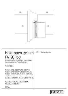
Wiring diagram FA CG 150
Hold-open system FA GC 150 Instructions for installation, commissioning, operation and maintenance RSZ 6, RSZ 7, TS 4000 R, TS 4000 RFS, TS 4000 R-IS, TS 5000 R, TS 5000 RFS, TS 5000 RFS KB, TS 5000 R-ISM /G/S/0, TS 5000 R-ISM EFS, Slimdrive EMD F/R*, Slimdrive EMD F/R-IS*, Powerturn F/R*, Powerturn F/R-IS*, Powerturn F/R-IS/TS* 141512_07 EN Wiring diagram GEZE hold-open system FA GC 150 Contents … 1 Symbols and illustrations … 2 Notes … Installation and electrical connection of the hold-open system … Installation of the lintel-mounted smoke switch … Protecting a smoke switch from contamination … Disposal … 3 Hold-open system FA GC 150 … … .1 … .2 … .3 Function … Hold-open system with separate smoke control unit RSZ 6, RSZ … Integrated hold-open systems … Classification in accordance with EN 14637 … Planning of fire detectors and manual trigger switches … Smoke detector or thermal detector … Number and installation of fire detectors … 10 Manual trigger switch … 11 … Technical data … 12 … .1 … .2 … .1 … .2 … .1 … .2 … .1 … .2 Hold-open system FA GC 150 … 12 Guidelines … 12 Power supply … 12 Lintel-mounted smoke switch GC 151 … 13 Wireless module GC 171 … 14 “Operating” mode … 16 “Set up wireless connection” mode … 18 Ceiling-mounted smoke detector GC 152 … 21 Ceiling-mounted thermal detector GC 153 … 22 Ceiling-mounted smoke detector ORS 142 … 23 Wireless ceiling-mounted smoke detector GC 172 … 24 Signalling … 25 Battery replacement … 25 Wireless thermal detector GC 173 … 25 Signalling … 26 Battery replacement … 26 Manual trigger switch UTA … 27 Wireless input module GC 175 … 27 Signalling … 28 Battery replacement … 28 … Wiring diagram … 29 … Mains connection … 29 … .1 … .2 … .3 … .4 … .1 … .2 … .1 … .2 … .3 … .1 … .2 Mains connection for protection rating I … 29 … 30 Mains connection for protection rating II Mains connection for Slimdrive EMD F/R versions* … 30 Mains connection for Powerturn F/R versions* … 30 Ceiling-mounted detector … 30 Ceiling-mounted detectors GC 152 and GC 153 … 30 Ceiling-mounted smoke detector ORS 142 … 33 Manual trigger switch or contact of the fire alarm system … 34 Manual trigger switch UTA … 34 Contact to the fire alarm system … 35 Contact of the fire alarm system and manual trigger switch UTA … 35 Wireless module GC 171 … 36 Wireless ceiling-mounted detector GC 172 or GC 173 and/or wireless input modules GC 175 … 36 Wireless ceiling-mounted detector GC 172 or GC 173 – manual trigger switch or fire detector contact wired … 37 GEZE hold-open system FA GC 150 … .3 … .1 … .2 … .3 … .1 … .2 … .3 … .4 … .5 … .6 … .7 … .8 … .9 … .10 … .11 … .12 … .13 Wireless ceiling-mounted detector wired – wireless input modules GC 175 … 37 Wireless input module GC 175 … 37 Manual trigger switch UTA … 38 Contact to the fire alarm system … 38 Contact of the fire alarm system and manual trigger switch UTA … 39 Alarm output … 39 Mutual triggering of two hold-open systems … 39 Hold-open device … 40 Hold-open system RSZ 6, RSZ … 40 Hold-open system TS 4000 R, TS 4000 RFS … 48 Hold-open system TS 4000 R-IS … 48 Hold-open system TS 5000 R … 49 Hold-open system TS 5000 R-ISM /G/S/0 … 49 Hold-open system TS 5000 R- ISM-EFS/ TS TS 5000 R-ISM/ … with free swing door closer … 50 Hold-open system TS 5000 RFS … 50 Hold-open system TS 5000 RFS-KB … 50 Hold-open system Slimdrive EMD F/R … 51 Hold-open system Slimdrive EMD F/R-IS* … 52 Hold-open system Powerturn F/R* … 52 Hold-open system Powerturn F/R-IS* … 53 Hold-open system Powerturn F/R-IS/TS* … 54 … Commissioning … 55 … .1 … .2 … .1 … .2 … Check the self-closing characteristic of the door … 55 1-leaf door … 55 2-leaf door … 55 Testing the smoke detectors … 55 GC 151 … 55 GC 152, ORS 142 and GC 172 … 55 Testing the thermal detectors GC 153 and GC 173 … 55 … Confirmation of conformity for the installation of the hold-open system … 56 … Acceptance test … 56 … Maintenance … 57 … Routine inspection / monthly inspection … 57 Annual testing and maintenance … 57 EN 14637 German institute for construction technology General construction technique permit: Z- … -2308 Z- … -2309 Certification office: BWU33 *The automatic swing door drives TSA 160 NT F, TSA 160 NT F EN7, TSA 160 NT F-IS, TSA 160 NT F-IS-TS, Slimdrive EMD-F, Slimdrive EMD-F-IS, Slimdrive EMD F/R, Slimdrive EMD F/R-IS, Powerturn F/R, Powerturn F/R-IS, Powerturn F/R-IS/TS, are hold-open devices/systems which are approved under the general construction technique permit Z- … -2308 or Z- … -2309, but their testing according to EN 14637 has not yet been completed. … Symbols and illustrations … GEZE hold-open system FA GC 150 Symbols and illustrations Warning notices In these instructions, warning notices are used to warn against material damage and injuries. XX Always read and observe these warning notices. XX Observe all measures marked with the warning symbol and warning word. Warning symbol – Warning word Meaning DANGER Danger to persons. Non-compliance will result in death or serious injuries. CAUTION Information to prevent property damage, to understand or optimise the operation sequences. Further symbols and means of representation Important information and technical notes are highlighted to explain correct operation. Symbol Meaning means “important note” means “additional Information” XX Symbol for an action: This means you have to do something. XX If there are several actions to be taken, keep to the given order. Abbreviations AL Alarm AS Ceiling-mounted detector (additional sensor) BMA Fire alarm system E Electric hold-open device EMC Electromagnetic compatibility FA Hold-open system FS Free swing function GC GEZE GND Reference potential (ground) HOD Hold-open device IS Integrated closing sequence ISM Integrated closing sequence (mechanical) KB Transom installation hinge side LED Light-emitting diode LK Luster terminal MRB Manual trigger switch (manual release button) NC Normally closed contact NO Normally open contact … R Electric hold-open device with lintel-mounted detector and power supply (hold-open system) RSZ Smoke control unit TS = Door closer UTA Manual trigger switch Colours BK black BN brown BU blue GN green RD red YE yellow WH white Notes úú In compliance with the manufacturer’s product liability as defined in the German “Product Liability Act”, the information contained in this brochure is to be noted and followed. Failure to comply releases the manufacturer from his statutory liability. úú To ensure personal safety, it is important to follow these safety instructions. úú Heed the installation instructions for the hold-open system and its assembly groups. úú The country-specific regulations are to be observed if used on fire and smoke protection doors. úú Keep these documents. … Installation and electrical connection of the hold-open system úú The hold-open system must be installed by trained specialists. Refer also to the installation instructions for the respective hold-open system. úú The connection of the hold-open system to the mains voltage must be carried out by a qualified electrician. úú Hold-open systems may not trigger an fire alarm signal for the building. úú Only the devices specified in the construction technique permit may be installed and connected. úú Before connecting hold-open system components to the power supply, the supply voltage must be switched off. … GEZE hold-open system FA GC 150 … Notes Installation of the lintel-mounted smoke switch úú Do not install the lintel-mounted smoke switch until construction work for commissioning of the holdopen system has been completed. úú The lintel-mounted smoke switch is a sensitive electronic product and must be protected against electrostatic discharge: úú Only take the lintel-mounted smoke switch out of the protective packaging directly before installation. úú Do not touch any electronic components. úú Interrupt the voltage supply before installing the lintel-mounted smoke switch. Fig. … .1 úú The lintel-mounted smoke switch is clipped into the housing of the hold-open system. Fig. … .2 … Protecting a smoke switch from contamination úú Do not remove the dust protection film or dust protection cap from the smoke switch until commissioning is about to take place. úú After the smoke switch has been installed and the dust protection removed, make sure no dust gets into the measuring chamber. This leads to increased contamination and can significantly shorten the service life of the smoke switch. úú The measuring chamber of a smoke switch must not be opened. Fig. … .1 … Disposal úú The hold-open system is made up of materials that should be sent for recycling. The individual components have to be sorted in accordance with their material type. The parts can be disposed of at the local recycling depot or by a scrap recycling company. úú In accordance with the German Battery Directive, we are obliged to inform you of the following in connection with the sale of batteries or rechargeable batteries respectively in connection with the delivery of devices containing batteries or rechargeable batteries: Rechargeable batteries and batteries must not be disposed of with household waste. Disposal with household waste is expressly forbidden according to the German Battery Directive. As the end-consumer, you are legally obliged to return used batteries. Please dispose of batteries at a municipal collection point or in store. Batteries obtained from us can be returned to us by mail. The address is: GEZE GmbH, Incoming Goods, Reinhold-Vöster-Str. 21-29, 71229 Leonberg/Germany. Batteries which contain harmful substances are identified by a symbol of a crossed-out rubbish bin. … Hold-open system FA GC 150 … GEZE hold-open system FA GC 150 Hold-open system FA GC 150 Function Directly after a fire or smoke protection door has been opened, it is closed again by the fitted door closer. This self-closing characteristic is cancelled in a controlled way by the hold-open system, so that a fire or smoke protection door can remain open permanently. In the event of a power failure, response by a fire detector or triggering by a push button, an open door is closed by the door closer. … 2 … 3 … Integrated hold-open system integrierte Festellanlage integrierte Festellanlage Smoke control unit RSZ6 integrierte Festellanlage integrierte Festellanlage Rauchschaltzentrale RSZ6 Rauchschaltzentrale RSZ6 Rauchschaltzentrale RSZ6Lintel-mounted Power supply Rauchschaltzentrale RSZ6 EnergieSturzmelder mitmit detector with trigger EnergieSturzmelder … 1 EnergieSturzmelder mit versorgung Auslösevorrichtung mechanism versorgung Auslösevorrichtung EnergieSturzmelder mit Feststellversorgung Auslösevorrichtung versorgung Auslösevorrichtung vorrichtung 1- . / 2- Funkmodul GC 171 Ceiling-mo unted detector Ceiling-mo unted detector … Hold-open device Feststell1-leaf/2-leaf FeststellFeststellvorrichtung vorrichtung … 1- vorrichtung 1-. / 2. / 21- . / 2- Wireless Funkmodul module GC 171 Funkmodul … GCFunkmodul 171171 GC GC 171 Wireless Wireless ceilingWireless ceilingceiling-moun Wireless ceilingmounted Ceiling-mo Manual mounted ted detector Wireless ceilingWireless mounted detector Ceiling-mo unted trigger detector Ceiling-mo Manual Manual mounted input … trigger … detector … Ceiling-mo Manual unted detector switch unted trigger detector module Manual unted trigger detector switch Wireless detector switch trigger detector switch ceiling-moun Wireless ceilingWireless ceilingCeiling-mo Manual switch Wireless ceilingted detector mounted mounted unted trigger Ceiling-mo Ceiling-mo Manual Manual Wireless Wireless ceilingmounted detector … 3 detector Ceiling-mo Manual detector switch unted trigger unted trigger input … mounted Manual detector unted trigger detector switch detector switch module detector trigger detector switch switch Wireless input module Wireless Wireless Wireless GC 175 input input Manual input module module trigger module … switch Wireless input module Wireless Wireless Wireless GC 175 input input Manual input … module module trigger module switch Manual Manual trigger Manual Manual trigger switch trigger trigger switch switch switch Manual Manual trigger Manual Manual trigger switch trigger trigger switch switch switch … 3 Fig. … .1 GEZE hold-open system FA GC 150 … Hold-open system FA GC 150 Hold-open system with separate smoke control unit RSZ 6, RSZ … The hold-open system RSZ 6, RSZ … comprising: úú Power supply (1) úú Power supply RSZ 6, RSZ … úú Lintel-mounted smoke switch with trigger mechanism (1) úú GC 151, lintel-mounted smoke switch úú Wireless module (1) for the wireless connection of ceiling-mounted detector and/or manual trigger switches úú GC 171, wireless module úú Ceiling-mounted detector (2) úú GC 152, smoke detector with relay base úú GC 153, thermal detector with relay base úú ORS 142, smoke detector with base úú GC 172, wireless smoke detector úú GC 173, wireless thermal detector úú Manual trigger switch (3) úú UTA, manual trigger switch úú GC 175, wireless input module úú Hold-open device (1) overhead door closer úú TS 4000 E link arm, electrohydraulic hold-open function úú TS 4000 EFS link arm with free swing function, electrohydraulic hold-open function úú TS 4000 E-IS link arm, 2-leaf with integrated closing sequence, electrohydraulic hold-open function for both leaves úú E guide rail electromagnetic hold-open function úú E-ISM guide rail 2-leaf with integrated closing sequence, electromagnetic hold-open function for both leaves úú E-ISM/G guide rail 2-leaf with integrated closing sequence, electromagnetic hold-open function for the active leaf úú E-ISM/S guide rail 2-leaf with integrated closing sequence, electromagnetic hold-open function for the passive leaf úú ISM-EFS guide rail 2-leaf with integrated closing sequence, electrohydraulic hold-open function for the active leaf with free swing function úú TS 5000 EFS guide rail with free swing function, electrohydraulic hold-open function Integrated door closers úú E guide rail Boxer electromagnetic hold-open function úú E-ISM guide rail Boxer 2-leaf with integrated closing sequence, electromagnetic hold-open function for both leaves úú ISM-EFS guide rail Boxer 2-leaf with integrated closing sequence, electrohydraulic hold-open function for the active leaf with free swing function úú Boxer EFS guide rail with free swing function, electrohydraulic hold-open function Floor spring úú TS 550 NV-E electrohydraulic hold-open function úú TS 550 E electromagnetic hold-open function úú TS 550 E-IS 2-leaf with integrated closing sequence control, electromagnetic hold-open function Hold-open magnet úú GT 50 R úú GT 60 R úú GT 63 R úú GT 70 R … Hold-open system FA GC 150 GEZE hold-open system FA GC 150 Automatic drives úú TSA 160 NT F* hydraulic swing door drive úú TSA 160 NT F-IS* hydraulic swing door drive, 2-leaf with integrated mechanical closing sequence úú Slimdrive EMD-F* electromechanical swing door drive úú Slimdrive EMD F-IS* electromechanical swing door drive, 2-leaf with integrated mechanical door closing sequence úú Powerturn F* electromechanical swing door drive úú Powerturn F-IS* electromechanical swing door drive, 2-leaf with integrated mechanical closing sequence úú Powerturn F-IS/TS* electromechanical swing door drive on the active leaf, door closer on the passive leaf with integrated mechanical closing sequence … Integrated hold-open systems In addition to the hold-open system with separate smoke control unit RSZ 6, RSZ 7, the following hold-open systems with integrated hold-open device available for overhead door closers: úú TS 4000 R link arm, electrohydraulic hold-open function úú TS 4000 RFS link arm with free swing function, electrohydraulic hold-open function úú TS 4000 R-IS link arm, 2-leaf with integrated closing sequence, electrohydraulic hold-open function for both leaves úú TS 5000 R guide rail, electromagnetic hold-open function or hold-open function with hold-open magnet úú TS 5000 R-ISM guide rail, 2-leaf with integrated closing sequence, electromagnetic hold-open function for both leaves úú TS 5000 R-ISM/G guide rail, 2-leaf with integrated closing sequence, electromagnetic hold-open function for the active leaf úú TS 5000 R-ISM/S guide rail, 2-leaf with integrated closing sequence, electromagnetic hold-open function for the passive leaf úú TS 5000 R-ISM/0 guide rail, 2-leaf with integrated closing sequence, without electromagnetic hold-open function in the guide rail úú TS 5000 R-ISM-EFS guide rail, 2-leaf with integrated closing sequence, electrohydraulic hold-open function for the active leaf with free swing function úú TS 5000 RFS guide rail with free swing function, electrohydraulic hold-open function úú TS 5000 RFS KB guide rail with free swing function, transom installation hinge side, electrohydraulic hold-open function úú Slimdrive EMD F/R* electromechanical swing door drive úú Slimdrive EMD F/R-IS* electromechanical swing door drive, 2-leaf with integrated mechanical closing sequence úú Powerturn F/R* electromechanical swing door drive úú Powerturn F/R-IS* electromechanical swing door drive, 2-leaf with integrated mechanical closing sequence úú Powerturn F/R-IS/TS* electromechanical swing door drive on the active leaf, door closer on the passive leaf with integrated mechanical closing sequence … GEZE hold-open system FA GC 150 … Hold-open system FA GC 150 Classification in accordance with EN 14637 Hold-open system No. … Class … Application class No. … Class … Permanent function Frequent use by the general public and other persons with little incentive to take care 500,000 test cycles No. … Class … Door type Swing doors No. … Class … No. … Class … Suitability for use on fire/ Suitable for use on fire/smoke protection doors smoke protection doors Safety Meets all requirements of EN 14637 No. … Class … Class … Class … Class … .1 German institute for construction technology No defined corrosion resistance (in connection with automatic drives) Moderate corrosion resistance in accordance with EN 1670 (in connection with the hold-open magnet GT 60 R) High resistance in accordance with EN 1670 (in connection with the hold-open magnets GT 50 R, GT 63 R and GT 70 R) Very high resistance in accordance with EN 1670 (in connection with all other GEZE hold-open devices) Planning of fire detectors and manual trigger switches Smoke detector or thermal detector Smoke detectors detect smoke. They work using the scattered light principle. A light transmitter and a light interface are arranged in the measuring chamber in such a way that no light reaches the interface in the normal case. If there are suspended particles (smoke) in the measuring chamber, these scatter part of the light onto the interface, which converts this into an electric signal. Accordingly, a smoke detector not only detects smoke but all other suspended particles and responds sensitively to contamination. Thermal detectors measure the ambient temperature and respond if the temperature exceeds a certain maximum value or increases quickly within a certain time. Usually, smoke and fire gases spread quickly when a fire breaks out. It is only later that the temperature increases. Therefore smoke detectors must be used for hold-open systems on fire protection doors on rescue routes. As far as possible, smoke detectors should generally be used for hold-open systems. In areas where disruption such as steam, dust, condensation or operation-related smoke development (workshops, kitchens) occurs, it may, however, be sensible to use thermal detectors rather than smoke detectors. … Hold-open system FA GC 150 … .2 GEZE hold-open system FA GC 150 Number and installation of fire detectors h Distance between lower edge of the lintel and ceiling or false ceiling (where a larger concentration of smoke is to be expected first in the event of a fire). Lintel-mounted smoke switch Ceiling-mounted detector Usually there must be at least one ceilingmounted detector - i.e. one pair of detectors - fitted in the rooms adjacent to the smoke opening – and at least one lintel-mounted detector on one side of the lintel over the active leaf above the smoke opening. If the following prerequisites are met, other installations are sufficient if appropriate smoke-permeable false ceiling … one lintel-mounted smoke switch úú if the distance h is smaller than 100 cm on both sides of the door and úú if the opening width of the swing door is smaller than 300 cm Fig. … . … one lintel-mounted smoke switch and one ceiling-mounted detector on each side of the door úú if the distance h is greater than 100 cm on at least one side of the door if appropriate smoke-permeable false ceiling or úú if the opening width of the swing door is greater than 300 cm … Fig. … . … Lintel-mounted smoke switch úú The lintel-mounted smoke switch is installed directly above the door, in the case of 2-leaf doors above the active leaf. úú The lintel-mounted smoke switch is installed in such a way that a minimum distance of … cm is observed between the upper edge of the smoke switch housing and the component above it. úú The lintel-mounted smoke switch is only suitable for wall installation, it must not be installed on the ceiling. úú If the lintel-mounted smoke switch is subject to disruption such as steam, dust, condensation or operationrelated smoke development, it can make sense to cover the smoke chamber of the lintel-mounted smoke switch and to install an additional thermal detector as lintel-mounted smoke switch above the door using an installation bracket instead (not permissible on rescue routes). Ceiling-mounted detector úú The ceiling-mounted detectors are installed on the ceiling above the door, the distance to the wall is between 50 cm and 250 cm. The distance to any installation is at least 50 cm. úú If the distance h on one side of the door is greater than 500 cm, the corresponding ceiling-mounted detector can be mounted on a projecting arm 50 cm in front of the wall and at least 350 cm above the lower edge of the lintel. úú In special ceiling situations (e.g. sloped ceilings, false ceilings, galleries) the fire detectors must be installed where a larger concentration of smoke is to be expected in the event of a fire. If in doubt, a fire protection planner or expert should be consulted. 10 GEZE hold-open system FA GC 150 … .3 Hold-open system FA GC 150 Manual trigger switch Optional manual trigger switch: The hold-open devices úú TS 4000 E, TS 4000 E-IS úú E guide rail, E-ISM guide rail, E-ISM/G guide rail, E-ISM/S guide rail úú E guide rail Boxer, E-ISM guide rail Boxer úú TS 550 NV-E, TS 550 E, TS 550 E-IS and the hold-open systems úú TS 4000 R, TS 4000 R-IS úú TS 5000 R, TS 5000 R-ISM, TS 5000 R-ISM/G, TS 5000 R-ISM/S, TS 5000 R-ISM/0 can be triggered by hand by closing the door leaves manually. A manual trigger switch can be installed as an option. Manual trigger switch mandatory: The hold-open devices úú TS 4000 EFS úú TS 5000 EFS úú ISM-EFS guide rail úú Boxer EFS úú ISM-EFS guide rail Boxer úú GT 50 R, GT 60 R, GT 63 R, GT 70 R úú TSA 160 NT F*, TSA 160 NT F-IS* úú Slimdrive EMD F*, Slimdrive EMD F-IS* úú Powerturn F*, Powerturn F-IS*, Powerturn F-IS/TS* and the hold-open systems úú TS 4000 RFS úú TS 5000 RFS, TS 5000 RFS-KB, TS 5000 R-ISM-EFS úú Slimdrive EMD F/R*, Slimdrive EMD F/R-IS* úú Powerturn F/R*, Powerturn F/R-IS*, Powerturn F/R-IS/TS* cannot be triggered by hand. For this reason, a manual trigger switch must be installed. Installation of the manual trigger switch úú Installation of the manual trigger switch in a clearly visible place in the direct vicinity of the door (not concealed by the door leaf). úú Recommended installation height of the manual trigger switch: 140 cm ± 20 cm. 11 Technical data … Technical data … Hold-open system FA GC 150 Protection rating (according to DIN EN 61140) IP rating (in accordance with DIN 60529) Ambient temperature … DIN EN 14637:2008-01 DIN 14677:2011-03 DIN 18263-4:2015-04 DIN EN 54-4:1997-12 DIN EN 54-5:2001-03 DIN EN 54-7:2006-09 DIN EN 54-18:2005-12 DIN EN 54-25:2008-06 DIN EN 1155:2006-06 DIN EN 62368-1 VDE 0868-1:2016-05 DIN EN 60950-1:2014-08; VDE 0805-1:2014-08 DIN EN 61000-6-2:2016-05; VDE 0839-6-2:2015-05 DIN EN 61000-6-3:2011-09; VDE 0839-6-3:2011-09 ETSI EN 300 220-2, V3. … ,2017-02 ETSI EN 301 489-1, V1. … :2011-09 II RSZ 6, RSZ … (if automatic swing door drives are used as a hold-open device, they are connected up as protecting rating I devices) TS 5000 R, TS 5000 RFS TS 5000 R-ISM /G/S/0 TS 5000 R-ISM EFS IP20, only for dry areas -5 °C to 50 °C General requirements and test regulations for the approval procedure for hold-open systems - version September 2015 Locks and building hardware - electrically controlled hold-open systems for fire/smoke protection doors - requirements, test methods, application and maintenance Servicing of electrically controlled hold-open systems for fire and smoke protection closers Locks and building hardware - door closers with controlled locking structure - Part 4: Swing door drives with self-closing function Fire detection and fire alarm systems - Part 4: Power supply equipment Fire detection and fire alarm systems - Part 5: Heat detectors - point detectors Fire detection and fire alarm systems - Part 7: Smoke detectors - Point detectors using scattered light, transmitted light or ionisation Fire detection and fire alarm systems - Part 18: Input/output devices Fire detection and fire alarm systems - Part 25: Components which use high-frequency connections Locks and building hardware - electrically controlled hold-open mechanisms for swing doors - requirements and test methods Audio/video, information and communication technology equipmentPart 1: Safety requirements Information technology equipment - Safety - Part 1: General requirements Electromagnetic compatibility (EMC) - Part 6-2: Generic standards - Interference immunity for industrial sectors Electromagnetic compatibility (EMC) - Part 6-3: Generic standards - Interference immunity for residence, business and commercial sectors as well as small-sized business Electromagnetic compatibility and Radio spectrum Matters (ERM); Short Range Devices (SRD); Radio equipment to be used in the 25 MHz to … 000 MHz frequency range with power levels ranging up to 500 mW; Part 2: Harmonized EN covering essential requirements under article … of the R&TTE Directive Electromagnetic compatibility and Radio spectrum Matters (ERM); Electromagnetic Compatibility (EMC) standard for radio equipment and services; Part 1: Common technical requirements Power supply Power supply - Cable length 230V / 24V - Cable length 230V / 24V - Cable length 230V / 24V Input voltage Input current Output voltage Output current 12 I TS 4000 R, TS 4000 RFS TS 4000 R-IS, TS 5000 RFS KB Slimdrive EMD F/R* Slimdrive EMD F/R-IS* Powerturn F/R* Powerturn F/R-IS* Powerturn F/R-IS/TS* Guidelines DIBt Guidelines:2015 … GEZE hold-open system FA GC 150 130 mm / 150 mm (ID 085391) 90 mm / 65 mm (ID 103354) 700 mm / 750 mm (ID 115818) 230 V AC, +10 % / -15 %, 50 Hz maximum 80 mA 24 V ± 0,5 V DC maximum 260 mA GEZE hold-open system FA GC 150 … Technical data Lintel-mounted smoke switch GC 151 Lintel-mounted smoke switch GC 151 Functional principle Input voltage Input current Installation position Output hold-open device Additional detectors Manual trigger switch Alarm output Test button Detector test ID 142250 Scatter light, adaption of the alarm threshold, no alarm saving (selfresetting as soon as there is no longer any smoke in the measuring chamber) 24 V ± 0,5 V DC maximum 15 mA Wall (lintel) installation, horizontal Transistor output, short-circuit proof Free-wheeling diode for inductive load, maximum 24 V, 200 mA in the event of an alarm switch-off of the hold-open device for at least … s Connection of up to … ceiling-mounted detectors using 3-line technology Line monitoring (can be switched off) using two terminating resistors (43 kΩ each) at the end of the cable Line monitoring (can be switched off) using terminating resistor (43 kΩ) at the end of the cable Potential-free relay output, changer maximum 24 V DC / maximum … A The hold-open device is switched off as long as the key is pressed (for at least … s) Reset of the smoke switch by activating the button Alarm triggering: with test button or with test aerosol Line monitoring may only be deactivated when used as a spare part in old systems without line monitoring (ORS 141). Switch the supply voltage off before changing the jumper setting (remove terminal clamp KL1). The new jumper setting only becomes active after the mains voltage has been switched back on again. Power supply without manual trigger switch External hold-open mechanism with manual trigger switch Manual trigger switch without ceiling-mounted detector Ceiling-mounted detector with ceiling-mounted detector Alarm output Measuring chamber Internal hold-open mechanism without line monitoring to the manual trigger switch and/or ceiling-mounted detector with line monitoring to the manual trigger switch and/or ceiling-mounted detector Jumper set Jumper not set Test button LED for state and fault display Fig. … .1 13 Technical data GEZE hold-open system FA GC 150 State / fault LED Voltage-free Off Alarm output AL_NC 10 AL_COM 11 AL_NO 12 Hold-open output KL1: 3-4 / KL3: 1-2 0V Normal operation Green 24 V Contamination (warning) The lintel-mounted smoke switch should be replaced. Contamination limit reached The lintel-mounted smoke switch must be replaced. RedRD 24 V GN Green 0V RedRD GN Green RedRD Fault lintel-mounted smoke switch The lintel-mounted smoke switch must be replaced. Off aus Short-circuit at the hold-open output Disconnect the lintel-mounted smoke switch from the supply voltage and eliminate the short-circuit. Supply voltage for lintel-mounted smoke switch too small Broken cable manual trigger switch1) RedRD Off aus 0V AL_NC 10 AL_COM 11 AL_NO 12 RedRD 0V 0V Off aus Supply voltage ceiling-mounted detector too small1) RedRD Short-circuit ceiling-mounted detector1) Off aus 0V Manual trigger switch activated2) Short-circuit manual trigger switch1) Yellow 0V Press the test button Yellow 0V Red AL_NC 10 Alarm lintel-mounted smoke switch Alarm ceiling-mounted detector AL_COM 11 Broken cable ceiling-mounted detector1) AL_NO 12 Ceiling-mounted detector removed 1) Display only if line monitoring is active (jumper J3) 2) Does not apply if the manual trigger switch is connected as a normally closed contact. When the normally closed contact is actuated, “broken cable manual trigger switch” is displayed. … Tab. … .1 Wireless module GC 171 Wireless module GC 171 Colour Dimensions (W × H × D) Installation position Input voltage Input current Function Number of wireless participants 14 0V ID 163051 RAL 7016 (anthracite grey) 177 mm × 30 mm × 18 mm Wall installation 24 V DC maximum 15 mA The wireless module GC 171 makes wireless communication possible between the lintel-mounted smoke switch GC 151 and various wireless devices (wireless smoke detector GC 172, wireless thermal detector GC 173 and wireless input module GC 175). The wireless module GC 171 forwards wireless signals to the lintelmounted smoke switch GC 151 as changes in resistance. These changes in resistance correspond to those of the ceiling-mounted detectors GC 152 and GC 153 and the manual trigger switch. An alarm triggered at a wireless module is indicated without delay (in less than 10 s) at the lintel-mounted smoke switch GC 151. Interference with a wireless device or a problem with communication is indicated in less than 100 s on the lintel-mounted smoke switch GC 151. The wireless module GC 171 can communicate with a maximum of … wireless devices (GC 172, GC 173 or GC 175). GEZE hold-open system FA GC 150 Technical data Signal transfer period Antenna Frequency range Range Number of frequency channels Modulation technique Radiated power PB1 60 s integrated … MHz to … MHz 10 m (100 m in space) … FSK (frequency shift keying) 10 dBm / 10 mW SW2 GC151 GC161 24V … GND … PB1 MRB … AS … SW2 SW2 PB1 SW2 GC161 SW2 LED2 LED2 LED2 LED2 SW2GC151 LED2 LED1 GC151 LED2 KL1 SW1 … GC161 24V GND … MRB … 24V … AS … GND … MRB … 4 ASKL1 KL1 LED11...LED16 SW1 LED1 LED11...LED16SW11...SW16 LED11...LED16 SW1 SW11...SW16 LED1 SW11...SW16 KL1 KL1AS KL1 KL1 PB1 Fig. … .1 AS AS Connection to the lintel-mounted smoke switch 24V Power supply GND Power supply MRB Manual trigger switch AS Ceiling-mounted detector Push button for mode selection “Operating” mode “Set up wireless connection” mode LED1x Wireless device LEDs … LEDs, one LED belongs to exactly one wireless device. SW1x Wireless device switches … sliding switches, one switch belongs to exactly one wireless device. LED2 Status LED Indicates the status of the GC 171. SW2 Selection of the lintel-mounted smoke switch SW2 is switched to ON for connection to lintel-mounted smoke switch GC 151. Always remove jumpers J1 and J2 from the GC 151. 15 Technical data … .1 GEZE hold-open system FA GC 150 “Operating” mode After the supply voltage has been switched on, the wireless module GC 171 is in “operating” mode. LED displays In “operating” mode the GC 171 monitors the set-up wireless connections and signals faults and alarms to the lintel-mounted smoke switch. Faults and alarms are also indicated on the status LED and the wireless device LEDs of the GC 171. The following table shows the states for various events which are signalled via the set-up wireless connections: úú of the wireless device LEDs of the GC 171 úú of the status LED of the GC 171 úú of the LED of the lintel-mounted smoke switch GC 151 úú of the alarm output and the hold-open output of the lintel-mounted smoke switch GC 151 The wireless module GC 171 indicates an event until the cause has been eliminated. If the cause of an event is no longer present, the wireless module GC 171 changes back to normal operation (the displays are deleted and 24 V is applied to the hold-open output of the lintel-mounted smoke switch again). Wireless module GC 171 (“operating” mode) Wireless State / connec- fault tion GC 171 Wireless device LED 1x flashes green good flashes yellow sufficient flashes red poor General fault Off Connection quality Lintel-mounted smoke switch GC 151 Status LED LED Off Green Yellow Red Alarm output AL_NC 10 AL_COM 11 AL_NO 12 Hold-open output KL1: 3-4 / KL3: 1-2 24 V 0V Off GC 172 GC 173 General fault Red Sabotage Loss of connection Low battery charge (warning) Off Red Red Off Yellow 0V Off Off Red Yellow Green AL_NC 10 AL_COM 11 AL_NO 12 24 V Off Contamination Red/green short (warning) Contamina- Red/green long tion limit reached Wireless detec- Red tor alarm GC 175 General Red fault, broken cable Off Loss of Red connection Off Low battery Yellow charge (warning) Off Contact (nor- Yellow mally open contact) activated, short-circuit Red Red Off Red AL_NC 10 AL_COM 11 AL_NO 12 0V 0V Red Off Yellow Green Yellow AL_NC 10 AL_COM 11 AL_NO 12 24 V 0V Tab. … .1 16 GEZE hold-open system FA GC 150 Technical data Connection quality If the wireless device switch is in the OFF position during “operating” mode, the corresponding wireless device LED indicates the connection quality to the corresponding wireless device: - LED is Off g no wireless connection is set up - LED flashes green every … s g good connection quality - LED flashes yellow every … s g sufficient connection quality - LED flashes red every … s g still connected but poor connection quality Connection interference is possible, the quality of the wireless connection should be optimised by changing the position of the wireless device. If the wireless device switch is in the OFF position in “operating” mode and the wireless device signals an event (a warning, a fault or an alarm), the wireless device LED indicates this event in compliance with the table above instead of the connection quality. General fault The wireless module GC 171 signals “general fault” if úú no wireless connection is set up, úú the set-up switch is in the ON position with GC 172, GC 173 or GC 175, úú a fault has occurred during smoke detection with GC 172, úú the connection to the termination resistor is interrupted with GC 175, úú the wireless module GC 171 is in the “set up wireless connection” mode. Sabotage The wireless module GC 171 signals “sabotage” if a wireless detector GC 172 or GC 173 has been removed from its base. Loss of connection If the wireless module GC 171 does not receive a new message from a set-up wireless device within 100 s of the last message, the wireless module signals “loss of connection” for the corresponding wireless connection. The wireless module GC 171 continues to monitor this wireless connection. If the wireless module sends a signal again in time, the wireless module GC 171 returns to “normal operation”. Low battery charge The wireless module GC 171 signals “low battery charge” if the voltage of the main battery of the corresponding wireless device falls to less than … V. Both batteries (main battery and slave battery) must be replaced. Contamination The wireless module GC 171 signals “contamination” if the inside of the smoke chamber is heavily soiled. The corresponding wireless smoke detector GC 172 should be replaced. Contamination limit reached The wireless module GC 171 signals “contamination limit reached” if the inside of the smoke chamber is too heavily soiled. The corresponding wireless smoke detector GC 172 must be replaced. Wireless detector alarm The wireless module GC 171 signals “wireless ceiling-mounted detector alarm” if the wireless smoke detector GC 172 or the wireless thermal detector GC 173 triggers. The signal is acknowledged automatically when the cause of the alarm is no longer present. The wireless module GC 171 returns to “normal operation”. Contact activated The wireless module GC 171 signals “contact activated” if the input of the wireless input module GC 175 is shortcircuited (when the connected contact is closed or in the event of short-circuit of the connection to the contact). The signal is acknowledged automatically when the short-circuit is no longer present. The wireless module GC 171 returns to “normal operation”. Event memory The wireless module GC 171 saves the last event for every connected wireless device. A new event overwrites the last event. In order to check whether an event has been saved for the wireless device, slide the corresponding wireless device switch to the ON position. If an event has been saved for this wireless device, the corresponding wireless device LED will then display this event as shown in the table above. If the wireless device LED is green, then no event has been saved for this wireless device. When the wireless device switch is slid back to the OFF position, any event saved is deleted. 17 Technical data … .2 GEZE hold-open system FA GC 150 “Set up wireless connection” mode In the “set up wireless connection” mode, new wireless connections can be set up to new wireless devices GC 172, GC 173 or GC 175. A maximum of … wireless connections can be set up. Pre-conditions úú All the wireless device switches of the wireless module GC 171 are in the OFF position. SW1x úú The set-up switch of the new wireless device is set to the ON position. úú The protective film is on the battery compartment of the new wireless device and the main battery for the new wireless device has not been fitted. After the supply voltage has been switched on, the wireless module GC 171 is in “operating” mode. Press the PB1 push button on the wireless module GC 171 briefly to change to the “set up wireless connection” mode. The status LED2 of the wireless module GC 171 is now permanently lit red. XX PB1 PB1 SW2 SW2 GC151 GC151 GC161 GC161 LED2 LED2 24V 11 24V GND22 GND MRB 33 MRB AS 44 AS Set up wireless connection XX Slide a free wireless device switch SW1x of the wireless module GC 171 to the ON position. If a connection has already been set up for the wireless device switch selected, this is overwritten by the following process. The corresponding wireless device LED1x starts to flash green. The wireless module GC 171 waits for the connection query for a new wireless device. If a wireless device does not respond within … minutes, the GC 171 cancels the connection attempt, the corresponding wireless device LED1x lights up red. To start the connection attempt again, slide the corresponding wireless device switch SW1x to the OFF position briefly, then slide it back into the ON position. The corresponding wireless device LED1x flashes green again for … minutes. XX Install batteries XX 18 Remove the protective film from the battery compartment of the new wireless device and install the main battery in the new wireless device (ensure correct polarity). KL1 KL1 SW1 SW1 SW1x LED1 LED1 LED1x GEZE hold-open system FA GC 150 Technical data Wireless ceiling-mounted detector GC 172 or GC 173: The LED of the new wireless ceiling-mounted detector flashes green twice first, then lights up yellow for one second and then flashes red four times. As soon as the LED goes out after that, the connection can be set up. Wireless input module GC 175: The LED of the new wireless input module flashes green once first, then lights up yellow for one second and then flashes red four times. As soon as the LED goes out after that, the connection can be set up. Slide the set-up switch on the new wireless device to the … position. After a short time, the LED of the new wireless device will flash green for a few seconds. The corresponding wireless device LED1x of the wireless module GC 171 lights up green permanently. XX ON If the LED on the new wireless device lights up red permanently, no connection has been made. XX In this case, remove the main battery from the new wireless device, slide the set-up switch on the new wireless device back and forward six times and start again with “Install batteries”. XX Fit the wireless ceiling-mounted detector to the base and close the housing of the wireless input module. XX Slide the wireless device switch SW1x of the wireless module GC 171 to the OFF position again. The colour of the flashing of the corresponding wireless device LED1x ndicates the quality of the wireless connection (see chap. … .1). XX Optimise the quality of the wireless connection if necessary by changing the position of the wireless device. The connection of the wireless module GC 171 to the new wireless device has been set up. XX Note the set-up connection (number of the assigned wireless device switch) on the new wireless device unit e.g. on its identification plate. XX To set up further wireless connections, continue with step “Set up wireless connection”. XX Press the PB1 push button on the wireless module GC 171 briefly to change to the “operating” mode. The status LED2 of the wireless module GC 171 goes off. SW1x PB1 PB1 LED1x SW2 SW2 GC151 GC151 GC161 GC161 LED2 LED2 24V 11 24V GND22 GND MRB 33 MRB AS 44 AS KL1 KL1 SW1 SW1 LED1 LED1 19 Technical data GEZE hold-open system FA GC 150 Delete all wireless connections All wireless connections already set up can be deleted in the “set up wireless connection” mode. After the supply voltage has been switched on, the wireless module GC 171 is in “operating” mode. All the wireless device switches SW1x are in the OFF position. Press the PB1 push button briefly to change to the “set up wireless connection” mode. The status LED2 of the wireless module is now permanently lit red. XX SW1x PB1 PB1 SW2 SW2 GC151 GC151 GC161 GC161 LED2 LED2 24V 11 24V GND22 GND MRB 33 MRB AS 44 AS XX Slide all … wireless device switches SW1x to the ON position. The wireless device LED1x light up yellow in succession until all the wireless device switches are in the ON position. They then flash red for … s. Within these … s, deletion of the wireless connections can be cancelled by sliding one or more wireless device switches back to the OFF position KL1 KL1 Press the PB1 push button briefly to change back to the “operating” mode. The status LED2 of the wireless module is now permanently lit yellow. LED1 LED1 SW1x Now all … wireless device LED1x are lit yellow permanently, all wireless connections are deleted XX Slide all … wireless device switches SW1x back to the OFF position. XX SW1 SW1 LED1x SW1x PB1 PB1 SW2 SW2 GC151 GC151 GC161 GC161 24V 11 24V GND22 GND MRB 33 MRB AS 44 AS KL1 KL1 20 SW1 SW1 LED1 LED1 LED2 LED2 GEZE hold-open system FA GC 150 … Technical data Ceiling-mounted smoke detector GC 152 Smoke detector with relay base GC 152 ID 139850 úú Relay base GC 150 B comprising úú Smoke detector GC 002 D Smoke detector GC 002 D ID 141458 Colour white, RAL 9016 Dimensions (with base, Ø × H) 110 mm × 67 mm Functional principle Scatter light, adaption of the alarm threshold, no alarm saving (self-resetting as soon as there is no longer any smoke in the measuring chamber) Insect grid prevents insects getting into the measuring chamber. Input voltage 24 V DC Input current maximum 20 mA Installation position Ceiling mounting Terminating resistors … × 43 kΩ, integrated, can be disconnected Alarm output potential-free relay output, normally closed contact maximum 24 V DC / maximum … A Detector test Alarm triggering úú with test magnet near the magnetic sensor (GEZE logo) with test aerosol The detector test using a test magnet tests the electrical components. The detector test which forms part of the regular testing of the hold-open system must be carried out using a test aerosol (see chap. … .2). German institute for construction technology Signalling LED Voltage-free Off Relay output 24V ASout ASin Normal operation Alarm Off Red 11 24V ASout ASin Tab. … .1 … Fig. … .1 … GC 150 B ASin ASout 24V GND … Fig. … .2 … 2 Breaking point (see chap. … ) Magnetic sensor for testing (behind the GEZE logo) … LED for displaying state 21 Technical data … GEZE hold-open system FA GC 150 Ceiling-mounted thermal detector GC 153 Thermal detector with base GC 153 comprising Thermal detector GC 003 D Colour Dimensions (with base, Ø × H) Functional principle Alarm temperature EN 54-5 classification Input voltage Input current Installation position Terminating resistors Alarm output Detector test Alarm triggering úú with test magnet near the magnetic sensor úú with heat detector testing device The detector test using a test magnet tests the electrical components. The detector test which forms part of the regular testing of the holdopen system must be carried out using a heat detector testing device (see chap. … ). German institute for construction technology Signalling LED Voltage-free ID 139881 úú Relay base GC 150 B úú Thermal detector GC 003 D ID 141459 white, RAL 9016 110 mm × 67 mm Alarm if the ambient temperature exceeds the alarm temperature or if the ambient temperature increases very quickly, no alarm saving (self-resetting as soon as the ambient temperature has dropped again) 57 °C A1R 24 V DC maximum 20 mA Ceiling mounting … × 43 kΩ, integrated, can be disconnected Potential-free relay output, normally closed contact maximum 24 V DC / maximum … A Off Relay output 24V ASout ASin Normal operation Off 11 Alarm Red 24V ASout ASin Fig. … .2 Tab. … .1 … 1 GC 150 B ASin ASout 24V GND … Fig. … .3 … 2 22 Breaking point (see chap. … ) Magnetic sensor for testing (behind the GEZE logo) … LED for displaying state GEZE hold-open system FA GC 150 … Technical data Ceiling-mounted smoke detector ORS 142 Ceiling-mounted smoke detector kit ORS 142 with úú … × smoke detector ORS 142 úú … × base ORS 143 A úú … × magnetic holder Ceiling-mounted smoke detector ORS 142 with úú Smoke detector ORS 142 úú Base ORS 143 A úú … × magnetic holder Colour Dimensions (with base, Ø × H) Functional principle úú Smoke detection úú Temperature sensor Input voltage Input current Installation position IP rating Ambient temperature Alarm output Magnetic holder Detector test ID 141715 ID 091069 white, RAL 9010 80 mm × 66 mm Scatter light, adaption of the alarm threshold, self-resetting 70 °C ±5 24 V DC maximum 22 mA Ceiling mounting IP42 -20 °C to 60 °C Potential-free relay output, normally closed contact maximum 24 V DC / maximum … A switches on in the last ceiling-mounted detector … × 43 kW Alarm triggering with test aerosol Signalling Voltage-free LED Off Relay output Normal operation Green … 5 Contamination (warning) The ceiling-mounted smoke detector should be replaced. Yellow YE … 5 Contamination limit reached The ceiling-mounted smoke detector must be replaced. Yellow YE Fault The ceiling-mounted smoke detector must be replaced. Alarm Yellow … 5 Red … 5 … 5 GN Green … 5 GN Green Tab. … .1 LED for displaying state ORS 142 Fig. … .1 Fig. … .2 Fig. … .3 23 Technical data … GEZE hold-open system FA GC 150 Wireless ceiling-mounted smoke detector GC 172 Wireless ceiling-mounted smoke detector GC 172 comprising: ID 195522 úú Base GC 170 B úú Wireless smoke detector GC 002 F úú Two batteries CR 123A (3 V DC) white, RAL 9016 110 mm × 65 mm Scatter light, adaption of the alarm threshold, no alarm saving (self-resetting as soon as there is no longer any smoke in the measuring chamber) prevents insects getting into the measuring chamber. Ceiling mounting Battery type Colour Dimensions (with base, Ø × H) Functional principle Insect grid Installation position Detector test To activate test mode: XX Move the test magnet near to the magnetic sensor (GEZE logo). The LED flashes green. Alarm triggering: XX Move the test magnet near to the magnetic sensor (GEZE logo) again. XX Trigger the alarm using the test aerosol. The detector test using a test magnet tests the electrical components. The detector test which forms part of the regular testing of the hold-open system must be carried out using a test aerosol (see chap. … .2). German institute for construction technology Battery life span Signal transfer period Antenna Frequency range Range Number of frequency channels Modulation technique Radiated power … years 60 s integrated … MHz to … MHz 10 m (100 m in space) … FSK (frequency shift keying) 10 dBm / 10 mW … 1 … 5 60 … 7 … 2 … 2 … 24 Magnetic sensor for testing (behind the GEZE logo) LED for displaying state Battery compartment cover … 5 … Battery compartment Batteries Set-up switch … 8 Sabotage contact Base GEZE hold-open system FA GC 150 … .1 Technical data Signalling The LED of the wireless ceiling-mounted smoke detector GC 172 indicates various states and events. State, event Switch on Start set-up of the wireless connection LED for displaying state lights up green for … s, then repeated red flashes green until the wireless connection is established Fault during set-up of the wireless connection lights up red Operation off Alarm flashes red ( … s on – … s off) Battery … discharged flashes orange ( … s on – … s off) Battery … discharged flashes green ( … s on – … s off) Both batteries discharged flashes orange/green alternately ( … s on – … s off) Other faults flashes orange/green alternately ( … s each) Manipulation off Loss of connection off Test mode – the detector reacts sensitively to aerosol pulses flashes green every second for … minute Tab. … . … .2 Battery replacement The wireless detector signals “low battery charge” to the wireless module GC 171 if the charge state of the batteries is no longer sufficient. Both batteries (5) always have to be replaced together. The set-up switch (6) for the wireless detector must not be activated. XX Take the wireless detector out of the base (8). XX Remove the battery compartment cover (3). XX Remove both batteries (5). XX Insert new batteries (type CR123A) – make sure polarity is correct. XX Replace the battery compartment cover (3). XX Insert the wireless detector into the base (8). XX Test the wireless detector. It can take up to a minute for the wireless detector to be ready for operation after battery replacement. … Wireless thermal detector GC 173 Wireless thermal detector GC 173 comprising: Battery type Colour Dimensions (with base, Ø × H) Functional principle Alarm temperature EN 54-5 classification Installation position Detector test ID 195523 úú Base GC 170 B úú Wireless thermal detector GC 003 F úú Two batteries CR 123A (3 V DC) white, RAL 9016 110 mm × 65 mm Alarm if the ambient temperature exceeds the alarm temperature or if the ambient temperature increases very quickly, no alarm saving (self-resetting as soon as the ambient temperature has dropped again) 57 °C A1R Ceiling mounting To activate test mode: XX Move the test magnet near to the magnetic sensor (GEZE logo). The LED flashes green. Alarm triggering: XX Move the test magnet near to the magnetic sensor (GEZE logo) again. Trigger the alarm using the heat detector testing device. The detector test using a test magnet tests the electrical components. The detector test which forms part of the regular testing of the hold-open system must be carried out using a heat detector testing device. German institute for construction technology Service life main battery Signal transfer period Antenna Frequency range (see chap. … ). … years 60 s integrated … MHz to … MHz 25 Technical data Range Number of frequency channels Modulation technique Radiated power GEZE hold-open system FA GC 150 10 m (100 m in space) … FSK (frequency shift keying) 10 dBm / 10 mW … 1 … 5 60 … 7 … 2 … 2 … Magnetic sensor for testing (behind the GEZE logo) LED for displaying state Battery compartment cover … 5 … Battery compartment Batteries Set-up switch … 8 Sabotage contact Base … .1 Signalling The LED of the wireless ceiling-mounted thermal detector GC 173 indicates various states and events. State, event Switch on Start set-up of the wireless connection Fault during set-up of the wireless connection Operation Alarm Battery … discharged Battery … discharged Both batteries discharged Other faults Manipulation Loss of connection Test mode – the detector reacts sensitively to heat LED for displaying state lights up green for … s, then repeated red flashes green until the wireless connection is established lights up red off flashes red ( … s on – … s off) flashes orange ( … s on – … s off) flashes green ( … s on – … s off) flashes orange/green alternately ( … s on – … s off) flashes orange/green alternately ( … s each) off off flashes green every second for … minute Tab. … . … .2 Battery replacement The wireless detector signals “low battery charge” to the wireless module GC 171 if the charge state of the batteries is no longer sufficient. Both batteries (5) always have to be replaced together. The set-up switch (6) for the wireless detector must not be activated. XX Take the wireless detector out of the base (8). XX Remove the battery compartment cover (3). XX Remove both batteries (5). XX Insert new batteries (type CR123A) – make sure polarity is correct. XX Replace the battery compartment cover (3). XX Insert the wireless detector into the base (8). XX Test the wireless detector. It can take up to a minute for the wireless detector to be ready for operation after battery replacement. 26 GEZE hold-open system FA GC 150 … Technical data Manual trigger switch UTA Type UTA, AS500 Manual trigger switch ID 116266 Surface-mounted box ID 120503 Spare resistor 43 kΩ ID 157093 Type of switching Changer Switching voltage Maximum 250 V Switching current maximum 10 A Terminating resistor 43 kΩ Close door 43kΩ Fig. … .1 Fig. … .2 … Wireless input module GC 175 Wireless input module GC 175 comprising: Battery set (VPE 10) Spare resistor … kΩ Main battery Slave battery Colour Dimensions (Ø × H) Functional principle Line length Line monitoring ID 163068 úú Wireless input module GC 175 úú Main battery and slave battery, resistor … kΩ ID 183282 ID 163229 Type CR 123A (3 V DC) Type CR 2032A (3 V DC) Matt black 52 mm × 32 mm úú signals the state of an external potential-free contact (normally open contact) to the GC 171 wireless module úú monitors the line to the contact for breaks 130 mm Termination resistor … kΩ at the end of the line Installation position Installation in flush-mounted or cavity box Installation in such a way that removing the wireless module and manual trigger switch is only possible after these two assemblies have been disconnected from one another (e.g. installation of the two assemblies in two different flush-mounted boxes) Service life main battery Signal transfer period Antenna Frequency range Range Number of frequency channels Modulation technique Radiated power … years 60 s integrated … MHz to … MHz 10 m (100 m in space) … FSK (frequency shift keying) … dBm (3 mW) German institute for construction technology 27 Technical data GEZE hold-open system FA GC 150 … 1 CR123A … ON … OFF … 3 … 7 CR2032 … 1 … 3 … Housing Antenna Antenna socket Set-up switch Fig. … .1 … 6 … 8 LED for displaying state Main battery Slave battery Housing tab CAUTION! Component at risk from electrostatic charge XX Do not touch the antenna! … .1 Signalling The LED of the wireless input module GC 175 indicates various states and events. State, event Switch on after removal of the insulation film or after the main battery has been inserted Start set-up of the wireless connection Fault during set-up of the wireless connection Operation Broken cable Main battery discharged Slave battery discharged Main and slave batteries discharged Other faults Contact closed, short-circuit LED for displaying state flashes 10 x green, then red briefly, then the LED is Off flashes … x green, … x yellow, … x red red Off Off flashes yellow ( … s on – … s off) flashes green ( … s on – … s off) flashes yellow/green alternately ( … s on – … s off) flashes yellow/green alternately ( … s off each) flashes … x red … .2 Battery replacement The wireless input module signals “low battery charge” to the wireless module GC 171 if the charge state of the batteries is no longer sufficient. Both batteries (main battery and slave battery) always have to be replaced together. XX Bend the tabs on the side of the bottom part of the housing open slightly and pull the top part of the housing up and off carefully (the antenna will be pulled out of the antenna socket at this point). XX Remove the main battery. XX Use a small screwdriver to carefully remove the slave battery. XX Slide the new slave battery (type CR2032A) into place – the positive pole faces upwards. XX Insert the new main battery (type CR123A) – make sure polarity is correct. XX Replace the top part of the housing carefully, making sure the antenna meets the antenna socket. XX Replace the top part of the housing in such a way that the two tabs engage again. XX Test the wireless input module. To do this, activate the connected contact. The hold-open system must trigger and the door leaf must close. The status LEDs of the wireless module GC 171 and the lintel-mounted smoke switch light up yellow. 28 GEZE hold-open system FA GC 150 … Wiring diagram úú úú úú úú úú úú úú úú … Wiring diagram Note the requirements for selection and installation of the fire detectors and manual trigger switches in chapter … . In addition, heed the installation instructions for the respective hold-open system. The connection of the hold-open system to the mains voltage must be carried out by a qualified electrician. Before working on the electrical system interrupt the power supply and check for safe isolation from the supply. When an Uninterruptible Power Supply is used, the system will still be under voltage even when disconnected from the mains. Only use the specified cable types. Marking of on-site cables in these instructions: … NYM-J, … × … mm2 … NYM-O, … × … mm2 or NYM-J, … × … mm2 … J-Y(ST)Y, … × … mm or J-Y(ST)Y, … × … mm, maximum length smaller than 15 m … J-Y(ST)Y, … × … mm or J-Y(ST)Y, … × … mm, maximum length smaller than … m … J-Y(ST)Y, … × … × … mm or J-Y(ST)Y, … × … × … mm, maximum length smaller than 15 m … J-Y(ST)Y, … × … × … mm or J-Y(ST)Y, … × … × … mm, maximum length smaller than … m … J-Y(ST)Y, … × … mm or J-Y(ST)Y, … × … mm, maximum length smaller than … m … J-Y(ST)Y, … × … × … mm or J-Y(ST)Y, … × … × … mm, maximum length smaller than … m Non-marked connections are system cables, only these may be used. The cables must be sufficiently mechanically protected and attached. Insulate wires that are not used. Mains connection úú The GEZE hold-open systems are devices of protection rating I or protection rating II in accordance with DIN EN61140. úú A 16 A circuit breaker must be provided on site (suitable for the electrical installation). úú The 230 V supply must be introduced into the connecting space doubly insulated (with cable sheath) at least … mm. úú Total power consumption at the power supply max. 260 mA. … .1 Mains connection for protection rating I Power supply for ID Cable length 230V / 24V TS 4000 R, TS 4000 RFS, TS 4000 R-IS, TS 5000 RFS KB 103354 90 mm / 65 mm are connected using a three-core cable NYM-J, 3x1.5 mm2. úú Devices of protection rating I The protective earth conductor is connected to the PE terminal. Power supply … GC 151 maximum Fig. … . … 29 Wiring diagram … .2 GEZE hold-open system FA GC 150 Mains connection for protection rating II Power supply for smoke control unit RSZ 6, RSZ … ID Cable length 230 V / 24 V 085391 130 mm / 150 mm TS 5000 R, TS 5000 RFS, TS 5000 R-ISM /G/S/0, TS 5000 R-ISM-EFS no. 115818 700 mm / 750 mm Devices of protection rating II are connected using a two core cable NYM-O, 2x1.5 mm2 . Connection can also be made using a three core cable NYM-J, 3x1.5 mm2 . The protective earth conductor must not be connected and must be permanently insulated (e.g. additional luster terminal or shrink hose). GC 151 Power supply maximum 260 mA Fig. … . … .3 Mains connection for Slimdrive EMD F/R versions* see chap. … .9 and … .10 … .4 Mains connection for Powerturn F/R versions* … Ceiling-mounted detector … .1 Ceiling-mounted detectors GC 152 and GC 153 see chap. … .11, … .12 and … .13 úú Note the requirements on the number and installation of ceiling-mounted detectors in chap. … . úú When ceiling-mounted detectors are connected, remove jumper J2 from the lintel-mounted smoke switch GC 151. úú The ceiling-mounted smoke detector GC 152 is made up of the smoke detector GC 002 D and the relay base GC 150 B. úú The ceiling-mounted thermal detector GC 153 is made up of the thermal detector GC 003 D and the relay base GC 150 B. úú Ceiling-mounted smoke detector with base GC 152, ID 139850 Ceiling-mounted thermal detector with base GC 153, ID 139881 Smoke detector GC 002 D, ID 141458 Thermal detector GC 003 D, ID 141459 úú The resistors for line monitoring are already installed in the relay base GC 150 B. The resistors can be disconnected using a breaking point. To do this, insert a screwdriver … mm through the hole on the back of the relay base into the slot of the PDB and turn it, the connection to the resistors breaks. Back of the relay base Fig. … . … The resistors for line monitoring and the alarm resistor are already installed in the relay base GC 150 B. The resistors for line monitoring are located on a PCB inside the relay base. These can be disconnected using a screwdriver as described. The visible resistor is the alarm resistor. This must not be disconnected. Alarm resistor do not disconnect Fig. … . … 30 GEZE hold-open system FA GC 150 German institute for construction technology Wiring diagram Ceiling-mounted detectors GC 152 and GC 153 with line monitoring The general construction technique permit requires the cable to the ceiling-mounted detectors to be monitored. Line monitoring is active if: úú jumper J3 of the lintel-mounted smoke switch to the measuring chamber is set (2-3 factory setting, see chap. … ). úú the breaking point in the first relay base GC 150 B is disconnected. úú the breaking point in the last relay base GC 150 B is not disconnected. The ASin and ASout cables must be laid separately or protected. … 5 A Fig. … . … Disconnect the breaking point in the base of the first ceiling-mounted detector . Ceiling-mounted thermal detector GC 153 as lintel-mounted detector with line monitoring úú If the lintel-mounted smoke switch GC 151 is subject to disruption such as steam, dust, condensation or operation-related smoke development, it can make sense to use a thermal detector as a lintel-mounted detector. See the relevant notes in chap. … . úú Install an additional thermal detector GC 153 as a lintel-mounted detector above the door using the fixing bracket DM GC. See the relevant notes in chap. … (fixing bracket, white, RAL 9016, ID 150264). úú Protect the smoke chamber of the integrated lintel-mounted smoke switch from contamination using a dust protection cap (ID 146407). Fig. … . … 31 Wiring diagram GEZE hold-open system FA GC 150 Connection of a ceiling-mounted thermal detector GC 153 as a lintel-mounted detector and two further ceiling-mounted detectors PLEASE NOTE When two floor springs TS 550 E are used, no more than two ceiling-mounted detectors may be connected. … 5 … Cover smoke chamber A Ceiling-mounted detector Ceiling-mounted detector A Ceiling-mounted detector as lintel-mounted detector Fig. … . … Disconnect the breaking point in the base of the first two ceiling-mounted detectors The ASin and ASout cables must be laid separately or protected. 32 . GEZE hold-open system FA GC 150 … .2 Wiring diagram Ceiling-mounted smoke detector ORS 142 The ceiling-mounted detector ORS 142 is made up of the smoke detector ORS 142 and the base ORS 143 A. Ceiling-mounted smoke detector kit ORS 142 with úú … × smoke detector ORS 142 úú … × base ORS 143 A úú … × magnetic holder Ceiling-mounted smoke detector ORS 142 with úú Smoke detector ORS 142 úú Base ORS 143 A úú … × magnetic holder German institute for construction technology ID 141715 ID 091273 Ceiling-mounted smoke detector ORS 142 with line monitoring The general construction technique permit requires line monitoring to the ceiling-mounted detectors. Line monitoring is active if jumper J3 of the lintel-mounted smoke switch to the measuring chamber is set (2-3 factory setting, see chap. … ). XX Fasten the magnetic holder in the base between terminal … and 6. Connection of the first ceiling-mounted detector must not be executed as a parallel branch line (supply and return line in the same cable) Terminal box AS Ceiling-mounted detector (additional sensor) GND Reference potential (ground) Fig. … . … 33 Wiring diagram … GEZE hold-open system FA GC 150 Manual trigger switch or contact of the fire alarm system úú Spare resistor 43 kΩ, ID 157093 … .1 Manual trigger switch UTA úú Manual trigger switch UTA, AS500, ID 116266 Surface mounting cap, single, AS500, ID 120503 úú When a manual trigger switch is connected, remove jumper J1 from the lintel-mounted smoke switch. úú Note the requirements on the installation of manual trigger switch in chap. … . The general construction technique permit requires line monitoring to the manual trigger switch if the connection of a manual trigger switch is mandatory according to the standard (see chap. … .3). Line monitoring is active if: úú jumper J3 of the lintel-mounted smoke switch to the measuring chamber is set (2-3, see chap. … ). úú a 43 kΩ resistor is connected in parallel in the manual trigger switch. XX Connect the manual trigger switch as a normally open contact. XX Connect the manual trigger switch as a normally closed contact. … 3 Fig. … . … Fig. … . … Several manual trigger switches with normally open contact are connected in parallel. Only connect the 43 kΩ resistor in the last one. … 3 Fig. … . … Several manual trigger switches with normally closed contact are connected in parallel. Only connect the 43 kΩ resistor in the last one. … 3 The cable to the first manual trigger switch (UTA) must be laid separately or protected. 34 Fig. … . … GEZE hold-open system FA GC 150 … .2 Wiring diagram Contact to the fire alarm system XX When a potential-free contact of the fire alarm system is connected, remove jumper J1 from the lintel-mounted smoke switch. Line monitoring is active if: úú jumper J3 of the lintel-mounted smoke switch to the measuring chamber is set (2-3, see chap. … ). úú a 43 kΩ resistor is connected in parallel at the contact of the fire alarm system. Potential-free normally open contact (BMA) Potential-free opener contact (BMA) … 3 Fig. … . … .3 Fig. … . … Contact of the fire alarm system and manual trigger switch UTA The general construction technique permit requires line monitoring to the potential-free contact of the fire alarm system and to the manual trigger switch. German institute for construction technology Line monitoring is active if: úú jumper J3 of the lintel-mounted smoke switch to the measuring chamber is set (2-3, see chap. … ). úú a 43 kΩ resistor is connected in parallel at the end of the cable. XX XX Remove jumper J1 of the lintel-mounted smoke switch. Connect the potential-free contact as a N/O contact. UTA Potential-free normally open contact (BMA) … 3 Fig. … . … XX Connect the potential-free contact as a normally closed contact. UTA Potential-free opener contact (BMA) … 3 Fig. … . … The cable to the potential-free contact (fire-alarm system) must be laid separately or protected. 35 Wiring diagram … GEZE hold-open system FA GC 150 Wireless module GC 171 30 M a n trig ual g swi er tch 30 … Cei l unt ing-m o e det d ect or Cei l unt ing-m o e det d ect or úú Wireless module GC 171, ID 163051 Wireless ceiling-mounted smoke detector GC 172 - ID 195522 Wireless ceiling-mounted thermal detector GC 173 - ID 195523 Wireless input module GC 175, ID 163068 Battery set GC 17x, ID 183282 Spare resistor … kΩ, ID 163229 úú Remove jumper J1 and J2 of the lintel-mounted smoke switch GC 151 (see chap. … ). úú Set jumper J3 of the lintel-mounted smoke switch to the measuring chamber (2-3, factory setting, see chap. … ). úú The area defined in Figure … . … must be kept free. Observe distances and specifications in section … .2. … inte g r i ert eF Rau es c t e h l s l c anl h altz age ent Ene r a le R ve rgier SZ6 s o rgu ng M a n trig ual g swi er tch W i r e mo less ce u i det nted lingect or Fig. … . … Wireless ceiling-mounted detector GC 172 or GC 173 and/or wireless input modules GC 175 Fun GC kmod 171 ul Wir e inp less u mo t dul e Wir e inp less u mo t dul e Stu r Aus zmeld löse er m v o r rich it tun g … .1 W i r e mo less ce u i det nted lingect or úú Cable length between lintel-mounted smoke switch and wireless module GC 171 maximum … m úú Set switch SW2 of the wireless module GC 171 to the ON position (see chap. … ). úú See chap. … .2 for how to set up the wireless connections. F s e t vor stellr 1- ichtun ./2 g - M a n trig ual g swi er tch M a n trig ual g swi er tch … Fig. … . … 36 Stu r Aus zmeld löse er m v o r rich it tun g Fun GC kmod 171 ul Wi r e mo less ce u i det nted linge ct or Fig. … . … Wi r e mo less ce u i det nted lingect or W i r e mo less ce u i det nted lingect or Wir e inp less u mo t dul e Fes t vor stellrich … tu . / … ng - M a n trig ual g swi er tch M a n trig ual g swi er tch … Wir e inp less u mo t dul e Fun GC kmod 171 ul Stu r Aus zmeld löse er m v o r rich it tun g inte gr i e r te F Rau est c e h l s l c anl h altz age ent Ene r a le R ve rgier SZ6 s o rgu ng M a n trig ual g swi er tch Fes t vor stellrich … tu . / … ng - C e i l unt ing-m o e det d ect or … C e i l unt ing-m o e det d e Wir ctor e inp less u mo t dul e M a n trig ual g swi er t c h M a n trig ual g swi er tch úú Ceiling-mounted detectors are connected as described in chap. … . inte gr i e r te F Rau e st c e h l s l c a nl h altz age e nt Ene r a le R ve rgier SZ6 s o rgu ng M a n trig ual g swi er t ch anu al ge r h úú Manual trigger switch or fire alarm contact are connected as described in chap. … . W i r e mo less ce u i det nted linge ct or Wir e inp less u mo t dul e M a n trig ual g swi er tch Wireless input module GC 175 … Wireless ceiling-mounted detector wired – wireless input modules GC 175 … .3 Wireless ceiling-mounted detector GC 172 or GC 173 – manual trigger switch or fire detector contact wired … .2 Wiring diagram GEZE hold-open system FA GC 150 Fig. … . … úú Wireless input module GC 175, ID 163068 Battery set GC 17x, ID 183282 Spare resistor … kΩ, ID 163229 úú See chap. … .2 for how to set up the wireless connections. úú The cable at the wireless input module GC 175 may only be extended to max. … m 37 Wiring diagram … .1 GEZE hold-open system FA GC 150 Manual trigger switch UTA úú Manual trigger switch UTA, AS500, ID 116266 Surface mounting cap, single, AS500, ID 120503 úú Note the requirements on the installation of manual trigger switch in chap. … . úú Installation in flush-mounted or cavity box úú Install in such a way that removing the wireless module and manual trigger switch is only possible after these two assemblies have been disconnected from one another (e.g. installation of the two assemblies in two different flush-mounted boxes). German institute for construction technology 2,2 k GC 175 … Fig. … . … Several manual trigger switches are connected in parallel. Only connect the … kΩ resistor in the last one. UTA UTA … 7 2,2 k GC 175 Fig. … . … The cable to the first manual trigger switch (UTA) must be laid separately or protected. … .2 Contact to the fire alarm system Line monitoring is active if: úú a … kΩ resistor is connected in parallel at the contact of the fire alarm system. úú Connect the potential-free contact as a normally open contact Potential-free contact (BMA) … GC 175 Fig. … . … 38 GEZE hold-open system FA GC 150 … .3 German institute for construction technology Wiring diagram Contact of the fire alarm system and manual trigger switch UTA The general construction technique permit requires line monitoring to the potential-free contact of the fire alarm system and to the manual trigger switch. Line monitoring is active if: úú a … kΩ resistor is connected in parallel at the end of the cable. úú Connect the potential-free contact as a normally open contact Potentialfreier Kontakt(BMA) (BMA) Potential-free contact UTA … 2,2 k … GC 175 Fig. … . … The cable to the potential-free contact (fire-alarm system) must be laid separately or protected. … Alarm output úú Potential-free relay output, changer, maximum 24 V, … A úú In normal operation the contact 11-12 is open, in the event of power failure or alarm closed. úú Do not supply alarm display from the hold-open system. 24 V external Alarm display GND external … Fig. … .1 Mutual triggering of two hold-open systems úú Two hold-open systems can trigger each other mutually. For this purpose, the alarm contact of the one lintelmounted smoke switch is connected with the input MRB of the other lintel-mounted smoke switch. úú If additional manual trigger switches are required, these are connected in parallel to the connection at the respective input MRB. úú Remove jumper J1 from both lintel-mounted smoke switches. German institute for construction technology The general construction technique permit requires monitoring of the lines between the two lintel-mounted smoke switches. Line monitoring is active if: úú jumper J3 of the two lintel-mounted smoke switches to the measuring chamber is set (2-3, see chap. … ), úú a 43 kΩ resistor is connected in parallel at both lintel-mounted smoke switches directly at the alarm output. 39 Wiring diagram GEZE hold-open system FA GC 150 … Fig. … .1 … Hold-open device úú External hold-open devices are connected to KL1 of the lintel-mounted smoke switch (screw-push-terminal). Internal hold-open devices are connected to KL3 of the lintel-mounted smoke switch (system plug-type connection). … .1 Hold-open system RSZ 6, RSZ … Door closer TS 4000 E, TS 4000 EFS Door leaf installation úú Connector box with plug-in drip loop, ID 052105 GC 151 Connector box … Door transmis- TS 4000 E, TS 4000 EFS sion 24 VDC±15% Rem. w <20% I=42 mA Fig. … . … Transom installation … 2 … Fig. … . … 40 GEZE hold-open system FA GC 150 Wiring diagram Door closer TS 4000 E-IS Door leaf installation úú Connector box with plug-in drip loop, ID 052105 GC 151 Connector box TS 4000 E-IS Door transmission Active leaf … Switch closed if active leaf open I=42 mA 24 VDC±15% Rem. w. <20% … Door transmission Passive leaf 24 VDC±15% Rem. w. <20% Fig. … . … I=42 mA Transom installation Active leaf … Switch closed if active leaf open … Passive leaf Fig. … . … E guide rail, E guide rail Boxer E guide rail … 24 VDC±15% Rem. w. <30% I=85 mA Fig. … . … 41 Wiring diagram GEZE hold-open system FA GC 150 E-ISM guide rail, E-ISM guide rail Boxer (E-ISM/G no hold-open function in the passive leaf, E-ISM/S no hold-open function in the active leaf) Connection board active leaf E hold-open device active leaf … 24 VDC±15% Rem. w. <30% I=85 mA E hold-open device active leaf 24 VDC±15% Rem. w. <30% Fig. … . … I=85 mA ISM-EFS guide rail, ISM-EFS guide rail Boxer úú No hold-open device for the passive leaf úú Connector box with plug-in drip loop, ID 052105 GC 151 Connector box (only with ISM-EFS guide rail) Door TS 5000 EFS / transmis- Boxer EFS sion … 24 VDC±15% Rem. w <20% I=42 mA/80 mA Fig. … . … Door closer TS 5000 EFS Door leaf installation úú Connector box with drip loop, ID 162723 GC 151 Connector box Door transmission TS 5000 EFS … 3 … 1 24 VDC±15% Rem. w <20% I=42 mA Fig. … . … 42 GEZE hold-open system FA GC 150 Wiring diagram Transom installation … 24 VDC±15% Rem. w <20% I=42 mA Fig. … . … Integrated door closer Boxer EFS Boxer EFS … 24 VDC±15% Restw. <20% I=80 mA Fig. … . … Floor spring TS 550 NV-E … 24 VDC±15% Rem. w <20% I=42 mA Fig. … . … Floor spring TS 550 E 24 VDC±10% Rem. w <20% I=100 mA Fig. … . … 43 Wiring diagram GEZE hold-open system FA GC 150 Floor spring TS 550 E-IS úú Connection PCB, ID 001102 úú Terminal box on site Active leaf Passive leaf 24 VDC±10% Rem. w <20% 24 VDC±10% Rem. w <20% I=100 mA I=100 mA Switch closed if active leaf open Terminal box Connection board … 6 Fig. … . … Hold-open magnets GT 50 R, GT 63 R, GT 70 R … 24 VDC±15% Rem. w <30% I=63 mA/68 mA 44 Fig. … . … GEZE hold-open system FA GC 150 Wiring diagram Hydraulic swing door drive TSA 160 NT F*, TSA 160 NT F EN7* Accessories TSA 160 NT F, ID 019654 Follow the wiring diagram for the TSA 160 NT swing door drive. … Reset button Fig. … . … Hydraulic swing door drive TSA 160 NT F-IS* Accessories TSA 160 NT F, ID 019654 Follow the wiring diagram for the TSA 160 NT swing door drive. … Reset button Fig. … . … 45 Wiring diagram GEZE hold-open system FA GC 150 Electromechanical swing door drive Slimdrive EMD F* Follow wiring diagram for the Slimdrive EMD swing door drive. … Reset button Latching action cam Fig. … . … Electromechanical swing door drive Slimdrive EMD F-IS* Follow wiring diagram for the Slimdrive EMD swing door drive. … 3 Reset button 46 Latching action cam Fig. … . … GEZE hold-open system FA GC 150 Wiring diagram Electromechanical swing door drive Powerturn F* Follow wiring diagram for the Powerturn swing door drive. … Powerturn F DCU8 DCU801 DCU802 DCU800 Latching action cam Reset button Electromechanical swing door drive Powerturn F-IS* Fig. … . … Follow wiring diagram for the Powerturn swing door drive. … 3 Powerturn F GF Powerturn F SF DCU8 DCU8 DCU801 DCU802 Reset button DCU801 DCU800 DCU802 DCU800 Latching action cam Fig. … . … 47 Wiring diagram GEZE hold-open system FA GC 150 Electromechanical swing door drive Powerturn F-IS/TS* Follow wiring diagram for the Powerturn swing door drive. … 3 … Door closer Hold-open magnet Reed switch Reed switch closed if passive leaf is closed Latching action cam Reset button … .2 Fig. … . … Hold-open system TS 4000 R, TS 4000 RFS … .3 Fig. … . … Hold-open system TS 4000 R-IS Active leaf Switch closed if active leaf open Second unit Passive leaf Fig. … . … 48 GEZE hold-open system FA GC 150 … .4 Wiring diagram Hold-open system TS 5000 R Fig. … . … .5 Hold-open system TS 5000 R-ISM /G/S/0 TS 5000 R-ISM/G - no hold-open function in the passive leaf TS 5000 R-ISM/S - no hold-open function in the active leaf TS 5000 R-ISM/0 - no hold-open function in the passive and active leaf Connection board for active leaf R-hold-open function active leaf R-hold open function passive leaf Fig. … . … 49 Wiring diagram … .6 GEZE hold-open system FA GC 150 Hold-open system TS 5000 R- ISM-EFS/ TS TS 5000 R-ISM/ … with free swing door closer úú No hold-open device for the passive leaf úú Connector box with plug-in drip loop, ID 052105 GC 151 Connector box Door transmission TS 5000 EFS … Fig. … . … .7 Hold-open system TS 5000 RFS úú Door leaf installation úú Connector box with drip loop, ID 162723 GC 151 Connector box Door transmission TS 5000 EFS … 3 … 1 Fig. … . … .8 Hold-open system TS 5000 RFS-KB úú Transom installation 50 Fig. … . … GEZE hold-open system FA GC 150 Hold-open system Slimdrive EMD F/R Follow wiring diagram for the Slimdrive EMD swing door drive. … GND … Reset button Latching action cam 24 V … 5 24 V GND … .9 Wiring diagram Fig. … . … 51 Wiring diagram GEZE hold-open system FA GC 150 … .10 Hold-open system Slimdrive EMD F/R-IS* Follow wiring diagram for the Slimdrive EMD swing door drive. 55 24 V … GND … 24 V GND … 3 Latching action cam Reset button Fig. … . … .11 Hold-open system Powerturn F/R* Follow wiring diagram for the Powerturn swing door drive. 55 24 V … GND … Powerturn F DCU802 Reset button 52 24 V DCU801 GND DCU8 DCU800 Latching action cam Fig. … . … GEZE hold-open system FA GC 150 Wiring diagram … .12 Hold-open system Powerturn F/R-IS* Follow wiring diagram for the Powerturn swing door drive. 55 24 V … GND … 33 Powerturn F GF Powerturn F SF DCU8 DCU8 DCU801 DCU802 Reset button DCU801 DCU800 DCU802 DCU800 Latching action cam Fig. … . … 53 Wiring diagram GEZE hold-open system FA GC 150 … .13 Hold-open system Powerturn F/R-IS/TS* Follow wiring diagram for the Powerturn swing door drive. 24 V … GND … GND HOD … 5 Door closer Powerturn F GF DCU8 Hold-open magnet PA DCU802 DCU800 SF GND 24 V 63 mA 55 56 DCU801 … PE2 Reed switch … 51 Reed switch closed if passive leaf is closed Latching action cam Reset button Fig. … . … 54 GEZE hold-open system FA GC 150 … Commissioning 1. 2. 3. Switch on the mains voltage. The state display of the lintel-mounted smoke switch lights up green. Remove the dust protection film or dust protection cap from the housing of the hold-open system so that the smoke openings are clear. Remove the protective covers from the ceiling-mounted detectors. … Check the self-closing characteristic of the door … .1 1-leaf door 1. 2. 3. … .2 Open the door leaf completely. The door leaf is held in the open position by the hold-open system. Activate the test button on the lintel-mounted smoke switch. The state display lights up yellow for approx. … s. The door leaf closes and snaps into the latch. If necessary, adjust the manual disengaging torque in the opened position: Open the door leaf completely. According to EN 1155, the disengaging torque should be between 40 Nm and 120 Nm at an opening angle of 90°. 2-leaf door 1. 2. 3. 4. … Commissioning Open both door leaves completely. The door leaves are held in the open position by the hold-open system. Activate the test button on the lintel-mounted smoke switch. The state display lights up yellow for approx. … s. The door leaves close, following the closing sequence. Both door leaves close completely and the active leaf snaps into the latch. If necessary, adjust the manual disengaging torque in the opened position: Open both door leaves completely. According to EN 1155, the disengaging torque should be between 40 Nm and 120 Nm at an opening angle of 90°. Push the active leaf out of the hold-open function by hand, the passive leaf closes automatically. The active leaf comes to a standstill and then closes when the passive leaf is closed. Testing the smoke detectors Test aerosol, ID 059168 Systems may only be tested with an aerosol that evaporates without leaving any residue. … .1 GC 151 Carry out the following steps within approx. … minutes: 1. Press the test button, the state display changes from green to yellow. Wait until the state display lights up green again. 2. Open the door leaf completely. The door leaf is held in the open position by the hold-open system. 3. Now spray the test aerosol from a distance of about 15 cm into the free smoke opening in short bursts lasting about … s with … s between bursts, covering the upper smoke opening of the smoke detector for this. The smoke detector must trigger (change of the state display from green to red). The door closes. … .2 GC 152, ORS 142 and GC 172 1. 2. … Fig. … . … Open the door leaf completely. The door leaf is held in the open position by the hold-open system. Spray the test aerosol from a distance of 10 cm to 15 cm into the free smoke opening in short bursts lasting about … s with 10 s between bursts. The smoke detector must trigger (change of the state display of the lintel-mounted smoke detector from green to red). The door closes. Testing the thermal detectors GC 153 and GC 173 1. 2. Open both door leaves completely. The door leaves are held in the open position by the hold-open system. Test the thermal detector GC 153 using a tester for heat detectors. The thermal detector must trigger (change of the state display of the lintel-mounted smoke detector from green to red). The door closes. The test can also be carried out using a hair dryer. The air flow must reach a temperature of at least 60 °C but must not exceed 90 °C. 55 Confirmationofconformityfortheinstallationofthehold-opensystem … GEZE hold-open system FA GC 150 Confirmation of conformity for the installation of the hold-open system The contractor who installed the hold-open system must issue a confirmation of conformity for each construction project, certifying that the hold-open system has been professionally installed with regard to all details and in compliance with all provisions of the respective general construction technique permit (and, if applicable, the provisions of the modification and supplementary notices) as well as the assembly instructions provided by GEZE. This confirmation must be entered in the GEZE log book for hold-open systems. Alternatively, this confirmation may be based on the model from the general construction technique permit. The declaration is to be sent to the client for any necessary forwarding to the responsible building inspectorate. … Acceptance test An official acceptance test must be carried out in order to ascertain the correct function and installation according to the regulation once the installation of the hold-open system has been completed at the set-up location. The operator must arrange this official acceptance test. The acceptance test may only be carried out by GEZE specialists, specialists authorised by GEZE (with GEZE expert training) or specialists from an official test centre named by DIBt in the approval procedure. The official acceptance test must include at least the following points: 1. It must be checked that the installed devices and device combinations of the hold-open system correspond to the devices and device combinations specified in the general construction technique permit. 2. It shall be verified that the marking of the installed equipment and equipment combinations conforms to the marking specified in the general construction technique permit or standard. 3. The interaction of all devices and device combinations must be checked on the basis of the general construction technique permit, whereby triggering must take place both by simulation of the fire characteristic the fire detector is based on as well as by hand. 4. It must be checked whether the closer is released for automatic closing if the hold-open system is not functional (e.g. through removal of a detector or power failure). After the official acceptance test has taken place, the operator must attach a sign (set 10 pcs. ID 79142) in the size 105 mm × 52 mm, which is provided by GEZE, in the direct vicinity of the closer stating the following: úú Hold-open system úú Number of the general construction technique permit úú Official approval through .. .. (company logo as well as month and year of the official approval) and must be affixed permanently. The operator is to be given a certificate for the successful official acceptance test; this must be kept by the operator. 56 GEZE hold-open system FA GC 150 … Maintenance … Routine inspection / monthly inspection Maintenance úú The hold-open system must be kept permanently in a good operating condition by the operator; in particular the door leaves must not be blocked (e.g. by wedges, chains or other objects which prevent the door leave closing automatically). úú In order to ensure that the hold-open system is in a good condition, a routine test must be carried out at regular intervals on site. If twelve monthly functional tests in succession do not reveal functional faults, the hold-open system only needs to be checked at intervals of … months. If a functional fault is established during the quarterly functional tests, serviceability is to be re-established without delay and proved through at least three successive monthly functional tests. úú This routine test may be carried out by anyone, following appropriate briefing through GEZE. The functional test of a hold-open system must contain at least the following elements: úú Check on the manual trigger (manual trigger switch or by manual disengagement if permitted); úú Check on triggering of the hold-open system by testing the fire detectors (see chap. 6); úú Check on automatic resetting of the fire detectors from the alarm state; úú Check whether environmental influences impair the function of the hold-open system installed; úú Check whether the environment in the direct vicinity of the hold-open system has a negative influence on it (e.g. occurrence of dust or steam); úú Check on whether constructional changes and/or interaction with other product groups in the direct vicinity of the hold-open system has a negative influence (e.g. later installation of suspended ceilings) and whether the positioning of the fire detectors complies with the general construction technique permit (see chap. … ); úú Check whether the fire protection or smoke protection closer is released for automatic closure after triggering. When wireless assemblies are used in the hold-open system: úú The quality of the wireless connections must be tested (see chapter … .2 Connection quality). Construction changes or new electronic assemblies in the direct vicinity of the hold-open system can interfere with the wireless connections. úú The charge state of the batteries in the wireless assemblies GC 172, GC 173 and GC 175 must be tested. An empty battery is indicated as a warning at the status LED of the wireless module GC 171 (see chap. … .1) Scope, result and time of the functional test must be documented in the GEZE log book for hold-open systems and made available to the operator. These records must be stored by the operator. The operator must be informed if obvious functional problems and/or damage to the fire protection or smoke protection closer occur. … Annual testing and maintenance úú In addition, the operator is responsible for the organisation of the testing and maintenance of all the components of the hold-open system, so that it is guaranteed that these components work properly and without interference. This testing and maintenance must be carried out at least once a year in accordance with the recommendations of the manufacturer. Scope, results and date of this annual testing must be recorded in the GEZE log book for hold-open systems which must be kept by the operator. úú Regular maintenance and testing may only be carried out by a specialist or a person trained for this purpose. Maintenance of the hold-open system must include the elements of a functional test in accordance with chapter … and the following additional elements: úú Check the correlation with documentation and general construction technique permit; úú Cleaning of the function-related components of a hold-open system, in as far as their contamination can lead to impairment; (the measuring chamber of a smoke detector must not be opened). úú Check whether the hold-open system is triggered in the event of a power failure; úú Check whether the hold-open system is triggered in the event of a fire detector being removed. When wireless assemblies are used in the hold-open system: úú Change the main battery and the slave battery of GC 175 in a 5-year cycle, even without “battery empty” display on the GC 171. Scope, result and time of the maintenance carried out must be documented and made available to the operator. 57 58 GEZE hold-open system FA GC 150 GEZE hold-open system FA GC 150 59 Germany GEZE GmbH Niederlassung Süd-West Tel. +49 (0) 7152 203 594 E-Mail: leonberg.de@geze.com GEZE GmbH Niederlassung Süd-Ost Tel. +49 (0) 7152 203 6440 E-Mail: muenchen.de@geze.com GEZE GmbH Niederlassung Ost Tel. +49 (0) 7152 203 6840 E-Mail: berlin.de@geze.com GEZE GmbH Niederlassung Mitte/Luxemburg Tel. +49 (0) 7152 203 6888 E-Mail: frankfurt.de@geze.com GEZE GmbH Niederlassung West Tel. +49 (0) 7152 203 6770 E-Mail: duesseldorf.de@geze.com GEZE GmbH Niederlassung Nord Tel. +49 (0) 7152 203 6600 E-Mail: hamburg.de@geze.com GEZE Service GmbH Tel. +49 (0) 1802 923392 E-Mail: service-info.de@geze.com Austria GEZE Austria E-Mail: austria.at@geze.com www.geze.at Hungary GEZE Hungary Kft. E-Mail: office-hungary@geze.com www.geze.hu Scandinavia – Sweden GEZE Scandinavia AB E-Mail: sverige.se@geze.com www.geze.se Baltic States – Lithuania / Latvia / Estonia E-Mail: baltic-states@geze.com Iberia GEZE Iberia S.R.L. E-Mail: info.es@geze.com www.geze.es Scandinavia – Norway GEZE Scandinavia AB avd. Norge E-Mail: norge.se@geze.com www.geze.no Benelux GEZE Benelux B.V. E-Mail: benelux.nl@geze.com www.geze.be www.geze.nl India GEZE India Private Ltd. E-Mail: office-india@geze.com www.geze.in Scandinavia – Denmark GEZE Danmark E-Mail: danmark.se@geze.com www.geze.dk Bulgaria GEZE Bulgaria - Trade E-Mail: office-bulgaria@geze.com www.geze.bg Italy GEZE Italia S.r.l. Unipersonale E-Mail: italia.it@geze.com www.geze.it Singapore GEZE (Asia Pacific) Pte, Ltd. E-Mail: gezesea@geze.com.sg www.geze.com China GEZE Industries (Tianjin) Co., Ltd. E-Mail: chinasales@geze.com.cn www.geze.com.cn GEZE Engineering Roma S.r.l E-Mail: italia.it@geze.com www.geze.it South Africa GEZE South Africa (Pty) Ltd. E-Mail: info@gezesa.co.za www.geze.co.za GEZE Industries (Tianjin) Co., Ltd. Branch Office Shanghai E-Mail: chinasales@geze.com.cn www.geze.com.cn GEZE Industries (Tianjin) Co., Ltd. Branch Office Guangzhou E-Mail: chinasales@geze.com.cn www.geze.com.cn GEZE Industries (Tianjin) Co., Ltd. Branch Office Beijing E-Mail: chinasales@geze.com.cn www.geze.com.cn France GEZE France S.A.R.L. E-Mail: france.fr@geze.com www.geze.fr Korea GEZE Korea Ltd. E-Mail: info.kr@geze.com www.geze.com Poland GEZE Polska Sp.z o.o. E-Mail: geze.pl@geze.com www.geze.pl Romania GEZE Romania S.R.L. E-Mail: office-romania@geze.com www.geze.ro Russia OOO GEZE RUS E-Mail: office-russia@geze.com www.geze.ru Switzerland GEZE Schweiz AG E-Mail: schweiz.ch@geze.com www.geze.ch Turkey GEZE Kapı ve Pencere Sistemleri E-Mail: office-turkey@geze.com www.geze.com Ukraine LLC GEZE Ukraine E-Mail: office-ukraine@geze.com www.geze.ua United Arab Emirates/GCC GEZE Middle East E-Mail: gezeme@geze.com www.geze.ae United Kingdom GEZE UK Ltd. E-Mail: info.uk@geze.com www.geze.com GEZE GmbH Reinhold-Vöster-Straße 21–29 71229 Leonberg Germany Tel.: 0049 7152 203 … Fax.: 0049 7152 203 310 www.geze.com
(PDF | 11 MB)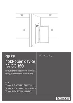
Hold-open system FA GC 160
GEZE hold-open device FA GC 160 GB Wiring diagram Instructions for installation, commissioning, operation and maintenance RSZ6, TS 4000 R, TS 4000 RFS, TS 4000 R-IS, TS 5000 R, TS 5000 RFS, TS 5000 RFS KB, TS 5000 R-ISM, TS 5000 R-ISM EFS … GEZE hold-open device FA GC 160 Table of contents … 1 Key to symbols … 2 Notes … Assembly and electrical connection of the hold-open device … Installation of lintel smoke switch … Protection of a lintel smoke switch against dirt accumulation … Waste disposal … 3 Hold-open device FA GC 160 … Operation … Hold-open device with separate smoke switch control unit RSZ6 … Integrated hold-open device … Classification according to EN 14637 … Fire alarm and manual release button design … … .1 … .2 … .3 Smoke detector or temperature sensor … Number and installation of the fire alarm … Manual release button … 10 … Technical data … 11 … Hold-open device FA GC 160 … 11 Guidelines … 11 Power pack … 11 Lintel smoke switch GC 161 … 12 Ceiling smoke detector GC 162 … 14 Ceiling temperature sensor GC 163 . … 15 Manual release button UTA … 16 … Wiring diagram … 17 … Mains connection … 17 … .1 … .2 Mains connection for protection class I Mains connection for protection class II … 17 . … 18 … Ceiling detector … 18 … .1 Ceiling detectors GC 162 and GC 163 … 18 … Manual release button UTA … 20 … .1 … .2 Manual release button UTA with line monitoring … 20 Manual release button UTA without line monitoring … 21 … Alarm output … 22 Hold-open device … 22 … .1 … .2 … .3 … .4 … .5 … .6 … .7 … .8 Hold-open device RSZ6 … 22 Hold-open systems TS 4000 R, TS 4000 RFS … 26 Hold-open system TS 4000 R-IS … 26 Hold-open system TS 5000 R … 26 Hold-open system TS 5000 R-ISM … 27 Hold-open system TS 5000 R-ISM-EFS … 27 Hold-open system TS 5000 RFS … 27 Hold-open system TS 5000 RFS-KB … 27 … Commissioning … 28 … Examination of the self-closing feature of the door … 28 … .1 … .2 1-leaf door … 28 2-leaf door … 28 … Testing the smoke detector . … 28 … .1 … .2 GC 161 … 28 GC 162 … 28 … Testing the temperature sensor … 29 … .1 GC 163 … 29 GEZE hold-open device FA GC 160 … Acceptance test … 29 … Maintenance … 30 … Routine check … 30 Annual inspection and maintenance … 30 EN 14637 Approval Nr.: Z- … -2192 Certifying authority: BWU33 … Key to symbols … GEZE hold-open device FA GC 160 Key to symbols Warning In these instructions, warnings are used to warn against material damage and injuries. XX Always read and observe these warnings. XX Follow all instructions marked with the warning symbol and the word WARNING. Warning symbol Warning DANGER – CAUTION Meaning Danger for people. Non-observance can result in death or serious injuries. Information to prevent damage to property and to understand and optimise workflow. Further symbols used in these instructions Important information and technical notes are emphasised to illustrate the correct operation. Symbol Meaning means “Important note“ means “Additional information” Symbol for a user action. Here you have to take an action. XX Observe the sequence if there are several action steps. XX Abbreviations AL AS E EMC FA FS GC GND HOD IS ISM KB LED LK MRB NC … Alarm Ceiling detector (additional sensor) Electrical hold-open Electromagnetic compatibility Hold-open system Free swing GEZE Reference potential (ground) Hold open device Integrated closing sequence Integrated closing sequence (mechanical) Transom mounting on hinge side Light-emitting diode Insulating screw joint Manual release button Normally closed contact NO R Normally open contact Electrical hold-open with lintel detector and power pack (hold-open system) RSZ Smoke switch control unit TS Door closer UTA Breaker switch Colours BK Black BN Brown BU Blue GN Green RD Red YE Yellow WH White Notes àà According to the definition of manufacturer's liability for his products in the Product Liability Act, the information contained in this brochure are to be followed. Ignoring this information absolves the manufacturer from his liability. àà For the safety of persons, it is important to follow these instructions. àà Follow the installation instructions for the hold-open system and its assemblies. àà When used in fire and smoke protection doors, all local regulations should be observed. àà Keep these documents. … Assembly and electrical connection of the hold-open device àà The assembly of the hold-open device should only be done by trained professionals. See installation instructions of the hold-open device. àà The connection of the hold-open device to the mains voltage must be performed by a qualified electrician. àà Hold-open devices should not trigger a fire alarm signal for the building. àà Only the devices approved in the certificate should be installed and connected. … GEZE hold-open device FA GC 160 … Notes Installation of lintel smoke switch àà Install the lintel smoke switch only after completion of construction at the time of the initial operation of the hold-open device. àà The lintel smoke switch is a sensitive electronic product and must be protected against electrostatic discharge: àà Remove the protective packaging of the lintel smoke switch only immediately before installation. àà Do not touch electronic components. àà Disconnect the power supply before installation of the lintel smoke switch. Fig.: … .1 àà The lintel smoke switch is clipped into the housing of the hold-open device. Fig.: … .2 … Protection of a lintel smoke switch against dirt accumulation àà The dust protection film or dust cover of a smoke switch should only be removed at the time of commissioning. àà After the installation of the smoke switch and removal of the dust cover, ensure that dust does not enter the measuring chamber. Otherwise it may result in increased dust accumulation that can significantly shorten the service life of the smoke switch. àà The measuring chamber of a smoke switch should not be opened. Fig.: … .1 … Waste disposal The hold-open device consists of materials that should be given for recycling. For this purpose, the individual components are to be sorted according to their materials. The parts can be disposed of at the local recycling centre or through a scrap recycling company. … Hold-open device FA GC 160 GEZE hold-open device FA GC 160 … Hold-open device FA GC 160 … Operation Immediately after opening a fire or smoke protection door, it is again closed by the mounted door closer. This selfclosing feature is overridden in a controlled manner by the hold-open device, so that a fire or smoke protection door can remain open indefinitely. In case of power failure, triggering of a fire alarm or activation by a button, an open door is closed by the door closer. Integrated hold-open system Smoke switch control unit RSZ … Power supply Lintel smoke switch with Triggering device … 1 Ceiling detector … Ceiling detector … Manual release button … Manual release button … 6 Hold-open device 1-wing/ 2-wing … Fig. … .1 GEZE hold-open device FA GC 160 … Hold-open device FA GC 160 Hold-open device with separate smoke switch control unit RSZ6 The hold-open device RSZ6 consists of: àà Power supply (1) àà Power pack RSZ6 àà Lintel smoke switch with triggering device (1) àà GC 161 àà Ceiling detector (2) àà GC 162, Smoke detector with base àà GC 163, Temperature sensor with base àà Manual release button (3) àà UTA, breaker switch àà Hold-open device (1) Overhead door closer àà TS 4000 E Rods, electro-hydraulic hold-open device àà TS 4000 EFS Rods with free swing function, electro-hydraulic hold-open device àà TS 4000 E-IS Rods, 2-wing with integrated closing sequence, electro--hydraulic hold-open device for both wings àà E guide rail Electromagnetic hold-open device àà E-ISM guide rail 2-wing with integrated closing sequence, electromagnetic hold-open device for both wings àà E-ISM/G guide rail 2-wing with integrated closing sequence, electromagnetic hold-open device for the active wing àà ISM-EFS guide rail 2-wing with integrated closing sequence, electro-hydraulic hold-open device for the active wing with free swing function àà TS 5000 EFS Guide rail with free swing function, electro-hydraulic hold-open device Integrated door closer àà E guide rail Boxer Electromagnetic hold-open device àà E-ISM guide rail Boxer 2-wing with integrated closing sequence, electromagnetic hold-open device for both wings àà ISM-EFS guide rail Boxer 2-wing with integrated closing sequence, electro-hydraulic hold-open device for the active wing with free swing function àà BOXER EFS Guide rail with free swing function, electro-hydraulic hold-open device Floor door closer àà TS 550 NV-E Electro-hydraulic hold-open device àà TS 550 E Electromagnetic hold-open device àà TS 550 E-IS 2-wing with integrated closing sequence control, electromagnetic hold-open device Holding magnet àà GT50R … Hold-open device FA GC 160 … GEZE hold-open device FA GC 160 Integrated hold-open device In addition to the hold-open device with separate smoke switch control unit RSZ6, the following locking systems with integrated hold-open device are available for overhead door closers: àà TS 4000 R Rods, electro-hydraulic hold-open device àà TS 4000 RFS Rods with free swing function, electro-hydraulic hold-open device àà TS 4000 R-IS Rods, 2-wing with integrated closing sequence, electro--hydraulic hold-open device for both wings àà TS 5000 R Guide rail, electromagnetic hold-open device àà TS 5000 R-ISM Guide rail, 2-wing with integrated closing sequence, electromagnetic hold-open device for both wings àà TS 5000 R-ISM Guide rail, 2-wing with integrated closing sequence, electromagnetic hold-open device for the active wing àà TS 5000 R-ISM-EFS Guide rail, 2-wing with integrated closing sequence, electro-hydraulic hold-open device for the active wing with free swing function àà TS 5000 RFS Guide rail with free swing function, electro-hydraulic hold-open device àà TS 5000 RFS-KB Guide rail with free swing function, transom mounting on hinge side, electro-hydraulic hold-open device … Classification according to EN 14637 GEZE D-71229 Leonberg +49 (0)7152/203-0 MM/JJJJ … 3/4 Input 230 V AC 0.08A Output 24 V DC 0.26A IP 30 Item … Class … Application class Item … Class … Continuous function Frequent use by the public and other persons with little incentive to care 500,000 test cycles Item … Class … Door type Three-wing revolving doors Item … Class … Suitable for use in fire and smoke protection doors Item … Class … Suitability for use in fire and smoke protection doors Safety Item … Class … Corrosion resistance High resistance according to EN 1670 (in conjunction with the holding magnets GT50R) Very high resistance according to EN 1670 (in conjunction with all other GEZE hold-open devices) Class … 8 Hold-open device RSZ6 Serial No. CA Identification No. BWU33 EN 14637 … 8 … 1 Meets all requirements of EN 14637 GEZE hold-open device FA GC 160 Hold-open device FA GC 160 … Fire alarm and manual release button design … .1 Smoke detector or temperature sensor Smoke detectors recognise smoke. They operate on the principle of diffused light. A light emitter and a light receiver are arranged in the measuring chamber in such a way that normally no light falls on the receiver. If there are suspended particles (smoke) in the measuring chamber, this scatters a portion of the light on the receiver, which converts it into an electrical signal. A smoke detector recognises not only smoke, but also all other suspended particles and is sensitive to pollution. Temperature sensors measure the ambient temperature and respond if the temperature exceeds a predetermined maximum value or increases dramatically within a certain time. Usually smoke and fumes spread quickly in case of a fire. The rise in temperature occurs only after a delay. That is why for fire doors on escape routes only smoke detectors should be used in hold-open devices. Smoke detectors should generally be used for hold-open devices as far as possible. In areas with interferences such as steam, dust, condensation or operation-related smoke emissions (workshops, kitchens), it makes more sense to use temperature sensors instead of smoke detectors. … .2 Number and installation of the fire alarm Distance between the lower edge of lintel and ceiling or false ceiling (where there is a fire, a larger concentration of smoke is to be expected first). h Lintel smoke switch Ceiling detector A lintel smoke switch àà if the distance h on either side of the door is less than 100 cm and … h < 100 cm < 10 cm If necessary, smoke-permeable false ceiling àà if the opening width of the door is less than 300 cm Fig.: … . … A lintel smoke switch and a ceiling detector on each side of the door àà if the distance h on at least one side of the door is more than 100 cm > 50 cm < 250 cm or àà if the opening width of the door is more than 300 cm < 10 cm > 50 cm < 250 cm If necessary, smoke-permeable false ceiling h ≥ 100 cm Fig.: … . … Hold-open device FA GC 160 GEZE hold-open device FA GC 160 Lintel smoke switch àà The lintel smoke switch is mounted directly above the door, above the active leaf for 2-leaf doors. The installation of the lintel smoke switch is done in such a way that there is a gap of at least … cm between ceiling or door lintel and upper smoke outlet. àà The lintel smoke switch is only suitable for wall mounting; do not mount on the ceiling. If the lintel smoke switch is exposed to disturbances such as steam, dust, condensation or operations-related smoke emission, it may be useful to cover the smoke chamber of the lintel smoke switch and instead, mount an additional temperature sensor as lintel smoke switch by means of a mounting bracket above the door (not permitted in escape routes). Ceiling detector àà The ceiling detectors are mounted on the ceiling above the door, the distance to the wall is between 50 cm and 250 cm. àà If the distance h on one side of the door is greater than 500 cm, then the corresponding ceiling detector can be mounted on a cantilever 50 cm from the wall and at least 350 cm above the lower edge of the lintel. … .3 Manual release button Manual release button optional: The hold-open devices àà TS 4000 E, TS 4000 E-IS àà E guide rail, E-ISM guide rail, E-ISM/G guide rail àà E guide rail Boxer, E-ISM E guide rail Boxer àà TS 550 NV-E, TS 550 E, TS 550 E-IS and the hold-open systems àà TS 4000 R, TS 4000 R-IS àà TS 5000 R, TS 5000 R-ISM, TS 5000 R-ISM/G can be ativated manually, by closing the door wing by hand. A manual release button can be installed optionally. Manual release button is prescribed: The hold-open devices àà TS 4000 EFS àà TS 5000 EFS àà ISM-EFS guide rail àà BOXER EFS, ISM-EFS guide rail Boxer àà GT50R and the hold-open systems àà TS 4000 RFS àà TS 5000 RFS, TS 5000 RFS-KB, TS 5000 R-ISM-EFS cannot be activated manually. Therefore, a manual release button should be mounted. Installation of the manual release button àà Install the manual release button at an easily visible position in the immediate vicinity of the door (not hidden by the door wing). àà Installation height of the manual release button: 140 cm ± 20 cm. 10 GEZE hold-open device FA GC 160 Technical data … Technical data … Hold-open device FA GC 160 … Protection class (according to DIN EN 61140) I Protection type (according to DIN EN 60529) Ambient temperature IP20, only for dry rooms II RSZ6, TS 5000 R, TS 5000 RFS, TS 5000 R-ISM, TS 5000 R-ISM EFS -5°C to 50°C Guidelines DIN EN 60950-1; VDE 0805-1:2011-01 DIN EN 61000-6-2; VDE 0839-6-2:2006-03 DIN EN 61000-6-3; VDE 0839-6-3:2007-09 DIN EN 1155:2003-04 DIN EN 14637:2008-01 DIBt-guidelines DIN EN 54-4:1997-12 DIN EN 54-5:2000-03 DIN EN 54-7:2006-09 DIN 14677:2011-03 … TS 4000 R, TS 4000 RFS, TS 4000 R-IS, TS 5000 RFS KB Information Technology Equipment - Safety - Part 1: General Requirements Electromagnetic compatibility (EMC) - Part 6-2: Generic standards Immunity for industrial environments Electromagnetic compatibility (EMC) - Part 6-3: Generic standards Emission standard for residential. commercial and light-industrial environments Building hardware - Electrically powered hold-open devices for swing doors - Requirements and test methods Building hardware - Electrically controlled hold-open systems for fire/ smoke door assemblies - Requirements, test methods, application and maintenance General requirements and test standards for the approval process for hold-open devices - July 2012 version Fire alarm systems - Part 4: Power supply equipment Fire alarm systems - Part 5: Heat sensors - Point-shaped detectors Fire alarm systems - Part 7: Smoke detectors - Point-shaped detectors according to the disffused light, transmitted light or ionisation principle Maintenance of electrically controlled hold-open systems for fire protection and smoke barriers Power pack Power pack - Cable length 230V / 24V - Cable length 230V / 24V - Cable length 230V / 24V Input voltage Input current Output voltage Output current 130mm / 150 mm (Mat. No. 085391) 90 mm / 65 mm (Mat. No. 103354) 700 mm / 750 mm (Mat. No. 115818) 230 V AC +10 % / -15%, 50 Hz Maximum 80 mA 24 ± … V DC Maximum 260 mA 11 Technical data … GEZE hold-open device FA GC 160 Lintel smoke switch GC 161 Lintel smoke switch GC 161 Functional principle Input voltage Input current Installation position Output hold-open device Additional detectors Manual release button Alarm output Reset button Detector test Mat. No. 140458 Diffused light, alarm threshold tracking, no alarm memory (self-resetting when there is no more smoke in the measuring chamber) 24 V DC Maximum 15 mA Wall (lintel) installation, horizontal Transistor output, short circuit proof Free-wheeling diode for inductive load Maximum 24 V, 200 mA In case of alarm, shutdown of the hold-open device for a minimum of … s Connect up to … ceiling detectors in 2-wire system Line monitoring by termination resistor ( … kΩ) at the end of the line Line monitoring (can be disabled) by termination resistor (43 kΩ) at the end of the line With active line monitoring connect the manual trigger switch as closer, with inactive line monitoring connect the manual trigger switch as opener. Potential free relay output, changeover contact maximum 24 V DC / maximum … A Shut-down of the hold-open device, as long as the button is pressed (for at least … s) Reset the smoke switch by pressing the button Alarm activation - with reset button - with test gas ON OFF Supply External hold-open device Manual release button Ceiling detector … Ceiling detector … Alarm output OFF ON OFF ON OFF ON No alarm if manual release button is active Alarm if manual release button is active Manual release button without line monitoring Manual release button with line monitoring Without ceiling detector With ceiling detector OFF ON Without manual release button With manual release button Bold Factory setting Measuring chamber Internal hold-open device Reset button LED display for status and fault indication Fig. … .1 12 GEZE hold-open device FA GC 160 Technical data Status / Error LED Without voltage Off AL_NC 11 0V Lintel smoke switch alarm Ceiling detector alarm RD AL_COM 12 0V AL_NO 13 Normal operation GN Dust accumulation (warning) The lintel smoke switch should be replaced. RD Dust limit is reached The lintel smoke switch should be replaced. RD Error lintel smoke switch The lintel smoke switch should be replaced. RD Short circuit at locking output Separate lintel smoke switch from the supply voltage and eliminate the short circuit. Supply voltage too low for lintel smoke switch Line breakage of manual release button1) Supply voltage too low for ceiling detector … Short circuit of ceiling detector … Ceiling detector … line breakage Ceiling detector … removed Supply voltage too low for ceiling detector … Short circuit of ceiling detector … Ceiling detector … line breakage Ceiling detector … removed Reset button actuated Manual release button actuated Short circuit of manual release button1) Alarm output Locking output KL1: 3-4, KL3: 1-2 24 V 24 V GN 0V GN 0V off 0V RD off RD AL_NC 11 AL_COM 12 AL_NO 13 0V off 0V RD off 0V RD off YE YE 0V DIP4=OFF AL_NC 11 AL_COM 12 AL_NO 13 0V DIP4=ON 1) Indication only in case of line monitoring AL_NC 11 Manual release button active (DIP3 = ON) AL_COM 12 AL_NO 13 Tab. … .1 13 Technical data … GEZE hold-open device FA GC 160 Ceiling smoke detector GC 162 Smoke detector with base GC 162 consists of Smoke detector GC 002 D Colour Dimensions (with base, DxH) Functional principle Insect screen Input voltage Input current Installation position Termination resistor Alarm resistance Current increase principle - No alarm - Alarm Detector test … mA 10 mA Alarm activation - with test magnet in the vicinity of the magnetic sensor (GEZE logo) - with testing gas Signalling LED Off Normal operation Off Alarm RD Without voltage Mat. No. 139882 Base GC 160 B Smoke detector GC 002 D Mat. No. 141458 white, RAL 9016 110 mm x 54 mm Diffused light, alarm threshold tracking, no alarm memory (self-resetting when there is no more smoke in the measuring chamber) prevents insects from entering the measuring chamber 24 V DC Maximum 10 mA Ceiling mounting … kΩ, integrated, separable … kΩ Current consumption … mA … mA 10 mA Tab. … .1 GC 160 B … 6,8kΩ GND … 1 … 14 Fig. … .1 Fig. … .2 Magnetic sensor for testing (behind GEZE logo) LED for status indication GEZE hold-open device FA GC 160 … Technical data Ceiling temperature sensor GC 163 Temperature sensor with base GC 163 consists of Temperature sensor GC 003 D Colour Dimensions (with base, DxH) Functional principle Alarm temperature EN 54-5 Class Input voltage Input current Installation position Termination resistors Alarm resistance Current increase principle - No alarm - Alarm Detector test Mat. No. 139883 Base GC 160 B Temperature sensor GC 003 D Mat. No. 141459 white, RAL 9016 110 mm x 54 mm Alarm if ambient temperature exceeds the alarm temperature or if the ambient temperature increases very quickly, no alarm memory (self-resetting when the ambient temperature has fallen again) 57°C A1R 24 V DC Maximum 10 mA Ceiling mounting … kΩ, integrated, separable … kΩ … mA 10 mA Alarm activation - with test magnet in the vicinity of the magnetic sensor (GEZE logo) - with heat detector test apparatus Signalling Without voltage LED Current consumption Off … mA Normal operation Off Alarm RD … mA 10 mA Tab. … .1 GC 160 B … 6,8kΩ GND … 1 … Fig. … .1 Fig. … .2 Magnetic sensor for testing (behind GEZE logo) LED for status indication 15 Technical data … GEZE hold-open device FA GC 160 Manual release button UTA Type Breaker switch Surface box Circuit type Circuit voltage Switching current Termination resistor UTA, AS500 Mat. No. 116266 Mat. No. 120503 one changeover Maximum 250V Maximum 10A 43 kΩ 43kΩ Fig. … .1 16 GEZE hold-open device FA GC 160 … Wiring diagram Wiring diagram àà àà àà àà Observe the requirements for selection and installation of fire detectors and manual alarm button in chapter … . Observe in addition the installation instructions of the respective hold-open device. The connection of the hold-open device to the mains voltage must be performed by a qualified electrician. Before carrying out work on the electrical system, disconnect voltage supply and check that it is free of voltage. If you use an uninterruptible power supply, the system is also under voltage with mains activation. àà Only use the specified cable types. àà Labelling of on-site cable in these instructions: (1) NYM-J, 3x1.5 mm2 (2) NYM-O, 2x1.5 mm2 or NYM-J, 3x1.5 mm2 (3) J-Y(ST)Y, 2x0.6 mm2 or J-Y(ST)Y, 2x0.8 mm2, maximum length less than 15 m (4) J-Y(ST)Y, 2x0.6 mm2 or J-Y(ST)Y, 2x0.8 mm2, maximum length less than … m (5) J-Y(ST)Y, 2x2x0.6 mm2 or J-Y(ST)Y, 2x2x0.8 mm2, maximum length less than 15 m (6) J-Y(ST)Y, 2x2x0.6 mm2 or J-Y(ST)Y, 2x2x0.8 mm2, maximum length less than … m Non-labelled connections are system cables, only these should be used. àà The cables should be adequately protected and secured mechanically. àà Insulate unused wires. … Mains connection àà The GEZE hold-open systems are devices of protection class I and protection class II according to DIN EN 61140. àà As a mains separation device, an on-site circuit breaker B 10 A should be used. àà The 230 V supply line is double insulated (with cable jacket), to be inserted at least … mm into the terminal area. àà Total current consumption in the power pack up to 260 mA. … .1 Mains connection for protection class I Power pack for Mat. No. Cable length 230V / 24V TS 4000 R, TS 4000 RFS, TS 4000 R-IS, TS 5000 RFS KB 103354 90 mm / 65 mm àà Appliances of the protection class I are connected with a three-core cable NYM-J, 3x1.5 mm2. The ground wire is connected to the PE terminal. Power pack GC 161 maximum PE Fig. … . … 17 Wiring diagram … .2 GEZE hold-open device FA GC 160 Mains connection for protection class II Power pack for Smoke switch control unit RSZ6 Mat. No. Cable length 230V / 24V 085391 130 mm / 150 mm TS 5000 R, TS 5000 RFS, TS 5000 R-ISM, TS 5000 R-ISM-EFS No. 115818 700 mm / 750 mm àà Appliances of the protection class II are connected with a two-core cable NYM-O.2x1.5 mm2. The connection can also be done with a three-core cable NYM-J … x … mm2. Then the ground wire should not be connected and must be insulated permanently (e.g. additional insulating screw joint or shrink tubing). Power pack GC 161 maximum Fig. … . … Ceiling detector àà Observe the requirements on the selection and installation of ceiling detectors in chapter … . àà When connecting ceiling detectors, set switch DIP … of the lintel smoke switch GC 161 to ON. … .1 Ceiling detectors GC 162 and GC 163 àà The ceiling smoke detector GC 162 consists of the smoke detector GC 002 D and the base GC 160 B. àà The ceiling temperature sensor GC 163 consists of the temperature sensor GC 003 D and the base GC 160 B. àà Ceiling smoke detector with base GC 162, Mat. No. 139882 Ceiling temperature sensor with base GC 163, Mat. No. 139883 Smoke detector GC 002 D, Mat. Nr. 141458 Temperature sensor GC 003 D, Mat. No. 141459 Fig. … . … 18 GEZE hold-open device FA GC 160 Wiring diagram Ceiling temperature detector GC 163 as lintel smoke switch àà If the lintel smoke switch GC 161 is exposed to disturbances such as steam, dust, condensation or operation-related fumes, it is reasonable to use a temperature sensor as lintel detector. See notes on this in chapter … . àà An additional temperature sensor GC 163 as lintel detector mounted above the door with mounting bracket DM GC. See notes on this in chapter … (mounting bracket, white, RAL 9016, Mat.-No. 150264). àà Protect the smoke chamber of the integrated lintel smoke switch against dirt accumulation with dust cap (Mat. No. 146407). Fig. … . … Connecting a ceiling temperature sensor GC 163 as lintel detector Fig. … . … Ceiling detector as lintel smoke switch 19 Wiring diagram GEZE hold-open device FA GC 160 Connecting a ceiling temperature detector GC 163 as lintel smoke switch and two other ceiling detectors Remove termination resistor on the ceiling temperature detector GC 163. Ceiling detector as lintel detector Ceiling detector Ceiling detector Fig. … . … Manual release button UTA àà Breaker switch UTA, AS500, Mat. No. 116266 Surface cap 1-way, AS500, Mat. No. 120503 àà When connecting a manual release button, set switch DIP … of the lintel smoke switch GC 161 to ON. àà Observe the requirements for the installation of manual release button in section … . … .1 Manual release button UTA with line monitoring The building authority approval requires the line monitoring of the manual release button, if the connection to a manual release button is based on the stipulated standard (see chapter … ). The line monitoring is active, if: àà switch DIP3 of the lintel smoke switch GC 161 is set to ON (see chapter … ). àà a 43 kΩ resistor is connected in parallel in the manual release button. 20 GEZE hold-open device FA GC 160 Wiring diagram Connect manual release button as a closer. Fig. … . … Several manual release buttons can be connected in parallel. Connect 43 kΩ resistor only in the last one. … .2 Fig. … . … Manual release button UTA without line monitoring The monitoring is not active if: àà switch DIP3 of the lintel smoke switch GC 161 is set to OFF (see chapter … ). Connect manual release button as an opener. Fig. 5. … .1 Several manual release buttons can be connected in parallel. Fig. … . … 21 Wiring diagram … GEZE hold-open device FA GC 160 Alarm output àà Potential free relay contact, changeover contact, up to 24 V, … A àà The contact 12-13 is open in normal operation, closed in case of power failure or alarm. àà Do not supply alarm display from the hold-open system. 24 V external Whether the alarm output is switched when operating the manual release button is set with the button DIP4 of the lintel smoke switch GC 161. (DIP4 = ON: Alarm upon actuation of the release button) Alarm display GND external Fig. … .1 … Hold-open device àà External hold-open devices are connected to KL1 of the lintel smoke switch (screw-plug terminal). Internal hold-open devices are connected to KL3 of the lintel smoke switch (system connector). … .1 Hold-open device RSZ6 Door closers TS 4000 E, TS 4000 EFS Door leaf mounting àà Junction box with pluggable cable transition, Mat. No. 052105 GC 161 Junction box Doorway TS 4000 E, TS 4000 EFS Fig. … . … Transom mounting 22 Fig. … . … GEZE hold-open device FA GC 160 Wiring diagram Door closer TS 4000 E-IS Door leaf mounting àà Junction box with pluggable cable transition, Mat. No. 052105 GC 161 Junction box TS 4000 E-IS Doorway Active wing Switch is closed, if active wing is open Junction box Doorway Inactive wing Fig. … . … Transom mounting GC 161 TS 4000 E-IS Active wing Switch is closed, if active wing is open Inactive wing Fig. … . … E guide rail, E guide rail Boxer GC 161 E guide rail Fig. … . … 23 Wiring diagram GEZE hold-open device FA GC 160 E-ISM guide rail , E-ISM guide rail Boxer Guide rail Active wing Switch is closed, if active wing is open Guide rail Inactive wing Fig. … . … ISM-EFS guide rail, ISM-EFS-guide rail Boxer àà No hold-open device for the inactive wing àà Junction box with pluggable cable transition, Mat. No. 052105 GC 161 Junction box Doorway TS 5000 EFS Fig. … . … Door closer TS 5000 EFS Door leaf mounting àà Junction box with pluggable cable transition, Mat. No. 052105 GC 161 Junction box Doorway TS 5000 EFS Fig. … . … Transom mounting 24 Fig. … . … GEZE hold-open device FA GC 160 Wiring diagram Integrated door closer BOXER EFS Fig. … . … Bottom door closer TS 550 NV-E Fig. … . … Bottom door closer TS 550 E GC 161 TS 550 E KL1 GND … HOD … BU L=3m RD – + 15 mA 100 mA Fig. … . … Bottom door closer TS 550 E-IS àà Connection board, Mat No. 001102 àà Connection box, on-site Inactive wing Active wing Switch is closed, if active wing is open Connection board Connection box Switch is closed, if inactive wing is in the vicinity of the closed position Fig. … . … 25 Wiring diagram GEZE hold-open device FA GC 160 Holding magnet GT50R … .2 Fig. … . … Fig. … . … Hold-open systems TS 4000 R, TS 4000 RFS GC 161 KL3 GND … 3 HOD … 2 15 mA … 42 mA … .3 Hold-open system TS 4000 R-IS GC 161 Active wing KL3 GND … 3 HOD … 2 … 42 mA KL1 15 mA GND … RD Switch is closed, if active wing is open LK L=2m TS 4000 R- Second unit TS 4000 E Inactive wing … 2 … 42 mA … .4 Fig. … . … Hold-open system TS 5000 R GC 151 GC 161 LK KL3 GND … WH HOD … RD 15 mA 85 mA Fig. … . … 26 GEZE hold-open device FA GC 160 … .5 Wiring diagram Hold-open system TS 5000 R-ISM For TS 5000 R-ISM/G, no hold-open device in the inactive wing GC 161 KL3 24 V GND … – HOD … + SF 15 mA Active wing WH – RD + 85 mA Switch is closed, if active wing is open LK Inactive wing RD WH 85 mA Fig. … . … .6 Hold-open system TS 5000 R-ISM-EFS àà No hold-open device for the inactive wing àà Junction box with pluggable cable transition, Mat. No. 052105 GC 161 Junction box Doorway TS 5000 EFS Fig. … . … .7 Hold-open system TS 5000 RFS àà Door leaf mounting àà Junction box with pluggable cable transition, Mat. No. 052105 GC 161 Junction box Doorway TS 5000 EFS Fig. … . … .8 Hold-open system TS 5000 RFS-KB àà Transom mounting GC 151 GC 161 KL3 15 mA GND … 3 HOD … 2 … 42 mA Fig. … . … 27 Commissioning … Commissioning 1. 2. 3. Switch on the mains voltage. The status indicator of the lintel smoke switch glows green. Remove dust protection film or dust cap of the housing of the hold-open system, so that the smoke outlets are free. Remove protective covers of the ceiling detector. … Examination of the self-closing feature of the door … .1 1-leaf door 1. 2. 3. … .2 Fully open the door leaf. Door leaf is kept in the open position by the hold-open system. Press the reset button of the lintel smoke switch. Status indication glows yellow for about … seconds. The door leaf closes and snaps into the latch. If necessary, set manual disengagement torque in the open position: Fully open the door leaf. The ejection torque should be, according to EN 1155, between 40 Nm and 120 Nm with an opening angle of 90°. 2-leaf door 1. 2. 3. 4. … GEZE hold-open device FA GC 160 Fully open both door leaves. Door leaves are kept in the open position by the hold-open system. Press the reset button of the lintel smoke switch. Status indication glows yellow for about … seconds. The door leaves close complying with the closing sequence. Both door leaves close completely and the active leaf snaps into the latch. If necessary, set manual disengagement torque in the open position. Fully open both door leaves. The ejection torque should be, according to EN 1155, between 40 Nm and 120 Nm with an opening angle of 90°. Move active leaf by hand from the hold-open position, inactive leaf closes automatically. Active leaf stops and also closes if inactive leaf is closed. Testing the smoke detector Test gas, Mat. No. 059168 … .1 GC 161 Carry out the following steps within about … minutes: 1. 2. 3. Press the reset switch, the status display changes from green to red. Wait until the status display lights up green again. Fully open the door leaf. Door leaf is kept in the open position by the hold-open system. Now spray the test gas from a distance of about 15 cm into the free smoke opening in short bursts lasting about … s with … s between bursts, covering the upper smoke opening for this. The smoke detector must trigger (change of status indicator from green to red). The door closes. … .2 GC 162 1. 2. 3. 28 Fig. … . … Fully open the door leaf. Door leaf is kept in the open position by the hold-open system. Spray test gas from a distance of 10 cm to 15 cm into the free smoke outlet in short 1-second bursts at an interval of 10 seconds. The smoke detector must trigger (change of status indicator from green to red). The door closes. GEZE hold-open device FA GC 160 … Testing the temperature sensor … .1 GC 163 1. 2. … Acceptance test Fully open both door leaves. Door leaves are kept in the open position by the hold-open system. Check temperature sensor GC 163 with a test apparatus for heat detectors. The temperature sensor must trigger (change of status indicator from green to red). The door closes. The test can also be carried out using a hair dryer. The air flow must reach a temperature of at least 60°C but must not exceed 90°C. Acceptance test After the ready-to-use installation of the hold-open system on site, its correct installation and proper operation must be confirmed by an acceptance test. The acceptance test must be arranged by the operator. The acceptance test must be performed only by GEZE professionals, experts authorized by GEZE, or professionals of a test centre designated by DIBt in the approval process. The acceptance test must include the examination of the following points: 1. It should be verified that the installed devices and additional fire detectors, if any, of the hold-open device comply with the stipulations in the general building authority approval. 2. It should be verified that the markings of the installed devices and additional fire detectors, if any, comply with the marking stated in the general building authority approval. 3. The interaction of all devices should be verified on the basis of the general building authority approval, whereby the release must take place both through simulation of the characteristics of fire underlying the functional principle of the detector and by hand. 4. It should be verified whether the barrier for the automatic closure is enabled when the hold-open device is inoperable (e.g. by removal of a detector or by a power failure). After successful acceptance, a signboard (Set 10 Pcs Mat No. 79142) in the dimensions 105 mm x 52 mm with the inscription: àà Hold-open device àà Approved by .. .. (Trademark as well as month and year of acceptance) should be mounted in the immediate vicinity of the barrier by the operator. A certificate should be issued to the operator on the successful completion of the acceptance test; it must be kept by the operator. 29 Maintenance … Maintenance … Routine check GEZE hold-open device FA GC 160 àà The hold-open system must be permanently maintained in good operating condition by the operator, especially by paying attention that the doors are not blocked (e.g. by wedges, chains or other items that prevent the automatic closing of the door leaf). àà To ensure that the hold-open system is in good condition, routine testing must be performed on site at regular intervals. If no functional defects are found in the twelve consecutive function tests with an interval of a month, then the hold-open device needs to be checked only every … months. If a functional defect is found in the quarterly function tests, the operability should be restored immediately and this should be verified by at least three consecutive monthly function tests. àà This routine check may be performed by anyone according to the appropriate instructions by GEZE. The function test of a hold-open device must include at least the following elements: àà Verification of manual release (manual release button, or if permitted by manual disengagement); àà Verification of the release of the hold-open device by testing the fire detector (see Chapter 6); àà Verification of the automatic resetting of the fire detector from the alarm status; àà Checking whether ambient influences impair the function of the integrated hold-open device; àà Checking whether the use in the immediate vicinity of the hold-open device exercises negative influences on it (such as the presence of dust or water vapour); àà Checking whether the function of the hold-open device is negatively influenced by structural changes and/ or by interaction with other assembly sections in the immediate vicinity of the hold-open device (e.g. retrofitting of suspended ceilings) and whether the positioning of the fire detectors comply with the approval (see Chapter … ); àà Checking whether the fire or smoke barrier will be enabled after release of the automatic closure. Extent, results and time of the conducted function test are to be documented in the GEZE test book for holdopen device and made available the operator. These records shall be kept by the operator. Upon determination of apparent malfunction and/or damage to the fire and/or smoke barrier, the operator must be informed. … Annual inspection and maintenance àà In addition, the operator is responsible for the organisation of inspection and maintenance of all components of the hold-open system, thus ensuring that these components work together properly and without interference. This inspection and maintenance must be carried out at least once a year according to the manufacturer‘s recommendations. Scope, results and time of this annual inspection must be recorded in the GEZE test book for hold-open device, which needs to be kept by the operator. àà The regular maintenance and testing must be performed by a qualified person or a person trained for that purpose. The maintenance of the hold-open device must include the elements of a function test as described in Section … and the following additional elements: àà Checking for compliance with the documentation and the building authority approval; àà Cleaning of the functionally relevant components of a hold-open device, provided the dirt accumulation can make a negative impact; (the measuring chamber of a smoke detector must not be opened). àà Verification of the release of the hold-open device during a power failure; àà Verification of release of the hold-open device upon removal of a fire detector. Scope, results and time of the performed maintenance must be documented and made available to the operator. 30 GEZE hold-open device FA GC 160 Maintenance 31 Germany GEZE Sonderkonstruktionen GmbH Planken … 97944 Boxberg-Schweigern Tel. +49 (0) 7930-9294-0 Fax +49 (0) 7930-9294-10 E-Mail: sk.de@geze.com Austria GEZE Austria E-Mail: austria.at@geze.com www.geze.at Baltic States www.geze.com GEZE GmbH Niederlassung Süd-West Tel. +49 (0) 7152-203-594 E-Mail: leonberg.de@geze.com GEZE GmbH Niederlassung Süd-Ost Tel. +49 (0) 89-120 07 42-50 E-Mail: garching.de@geze.com GEZE GmbH Niederlassung Ost Tel. +49 (0) 30-47 89 90-0 E-Mail: berlin.de@geze.com GEZE GmbH Niederlassung Mitte/Luxemburg Tel. +49 (0) 6171-63610-0 E-Mail: frankfurt.de@geze.com GEZE GmbH Niederlassung West Tel. +49 (0) 201-83082-0 E-Mail: essen.de@geze.com GEZE GmbH Niederlassung Nord Tel. +49 (0) 40-2 19 07 16-13 E-Mail: hamburg.de@geze.com GEZE Service GmbH Tel. +49 (0) 18 02/92 33 92 E-Mail: service-info.de@geze.com GEZE GmbH Reinhold-Vöster-Straße 21–29 71229 Leonberg Germany Benelux GEZE Benelux B.V. E-Mail: benelux.nl@geze.com www.geze.be www.geze.nl Bulgaria GEZE Bulgaria - Trade www.geze.bg China GEZE Industries (Tianjin) Co., Ltd. E-Mail: Sales-info@geze.com.cn www.geze.com.cn GEZE Industries (Tianjin) Co., Ltd. E-Mail: chinasales@geze.com.cn www.geze.com.cn GEZE Industries (Tianjin) Co., Ltd. E-Mail: chinasales@geze.com.cn www.geze.com.cn GEZE Industries (Tianjin) Co., Ltd. E-Mail: chinasales@geze.com.cn www.geze.com.cn France GEZE France S.A.R.L. E-Mail: france.fr@geze.com www.geze.fr Tel.: 0049 7152 203-0 Fax: 0049 7152 203-310 www.geze.com Hungary GEZE Hungary Kft. www.geze.hu Iberia GEZE Iberia S.R.L. E-Mail: info@geze.es www.geze.es India GEZE India Private Ltd. www.geze.in Italy GEZE Italia S.r.l E-Mail: italia.it@geze.com www.geze.it GEZE Engineering Roma S.r.l E-Mail: roma@geze.biz www.geze.it Poland GEZE Polska Sp.z o.o. E-Mail: geze.pl@geze.com www.geze.pl Romania GEZE Romania S.R.L. www.geze.ro Russia OOO GEZE RUS www.geze.ru Scandinavia – Sweden GEZE Scandinavia AB E-Mail: sverige.se@geze.com www.geze.se Scandinavia – Norway GEZE Scandinavia AB avd. Norge E-Mail: norge.se@geze.com www.geze.no 141515-01 Scandinavia – Finland Scandinavia AB www.geze.com Scandinavia – Denmark GEZE Danmark E-Mail: danmark.se@geze.com www.geze.dk Singapore E-Mail: gezesea@geze.com.sg www.geze.com South Africa GEZE Distributors (Pty) Ltd. E-Mail: info@gezesa.co.za www.geze.co.za Switzerland GEZE Schweiz AG E-Mail: schweiz.ch@geze.com www.geze.ch Turkey GEZE Kapı ve Pencere Sistemleri www.geze.com Ukraine GEZE Ukraine TOV www.geze.ua United Arab Emirates/GCC GEZE Middle East E-Mail: geze@emirates.net.ae www.geze.ae United Kingdom GEZE UK Ltd. E-Mail: info.uk@geze.com www.geze.com
(PDF | 3 MB)
ECchain DGNB product verification
Reference: D12-1602 / … .2015 Product Declaration - DGNB New Construction Office and Administration Buildings (NBV12) MANUFACTURER GEZE GmbH PRODUCT NAME Ecchain Product Characteristics Electric chain drive for daily aeration and ventilation for vertically installed windows with inward and outward opening bottom-hung, top-hung and side-hung casements. Direct opener in 230V version.The stroke can be adjusted via the cable connection on the drive to 200 and 400 mm. The drive is equipped with built-in limit switches and overload protection. Overload cut-off is controlled electronically. Drive brackets and chain attachments allow easy installation from the front. Stroke: 200 and 400 mm Tensile force/pressure: 250 N/250 N Voltage: 230 V AC. Product Rating ▪ The product meets the requirements of quality level … to … and contributes to achieve 100 (of max. 100 achievable) checklist points according to criterion 'ENV1.2 Local Environmental Impact'. ▪ The product does not lead to toxic or corrosive fumes in case of fire. Hence this product contributes to achieve 20 (of max. 20 achievable) checklist points according to criterion 'SOC … Safety and Security'. The product contains the following components: Mass per unit [%] K1 Steel parts 61% K2 Copper 2% K3 Zinc die-cast 2% K4 Plastics 35% About DGNB Products - www.dgnb.de This declaration helps to assess products easily according the certification system DGNB. Products are not reviewed or certified by DGNB. DGNB credit requirements cover the performance of materials in aggregate, not the performance of individual products or brands. Therefore the project team or the manufacturer is responsible to declare the compliance with the project requirements to achieve DGNB points. Detailed information are on the next pages. Notice: This declaration is a product of HOINKA GmbH. This data sheet is published in the online database greenbuildingproducts.eu. The distribution by third parties is prohibited. This declaration is no official certificate in terms of DGNB. The contents are based on manufacturer specifications. In spite of a diligent treatment of all information HOINKA GmbH cannot guarantee the actuality or correctness of the published data. The interpretation of the DGNB criteria requirements can differ and depend on the project and the scope of application. In spite of a diligent treatment of all information HOINKA GmbH cannot guarantee the correctness of evaluation in terms of the DGNB requirements. The user of this declaration, the consumer of the product and the consultant/planner, who is advising this product in any construction projects, is responsible by himself to proof all data published in this document and to verify the permissibility for the designated application. The content of this data sheet does not manifest any legal relationship. With the publication of a new edition, this declaration can no longer be considered to be valid. The latest version is available in the internet. HOINKA GmbH ▪ greenbuildingproducts.eu ▪ Lembergweg 7/1 ▪ 71067 Sindelfingen ▪ Tel. +49 7031 7659-441 ▪ Fax +49 7031 7659-443 ▪ www.greenbuildingproducts.eu ▪ contact@greenbuildingproducts.eu ▪ Geschäftsführer: Dipl.-Ing. Thomas Hoinka MANUFACTURER GEZE GmbH PRODUCT NAME Ecchain Product assessment of complete system Topic Number ENV1.1 ENV1.2 Criteria Relevance Reference: D12-1602 / … .2015 Product Declaration - DGNB New Construction Office and Administration Buildings (NBV12) Evaluation Life cycle Assessment - Emissions Local environmental impact ENV1. … Responsible procurement (Wood) ENV1. … Responsible procurement (Formwork) ENV1. … Responsible procurement (Natural Stone) Quality Level … is fulfilled Environmental Quality (ENV) Economic Quality (ECO) Sociocultural and Functional Quality (SOC) Technical Quality (TEC) ENV2.1 Life cycle Assessment - Primary Energy ENV2.2 Potable water demand and wastewater volume ENV2.3 Land Use ECO1.1 Building-related life-cycle costs ECO2.1 Suitability for conversion ECO2.2 Marketability SOC1.1 Thermal Comfort SOC1.2 Indoor Air Quality SOC1.3 Acoustic Comfort SOC1.4 Visual Comfort SOC1.5 Occupant control SOC1.6 Quality of outdoor spaces SOC1.7 Safety and security SOC2.1 Access for all SOC2.2 Public access SOC2.3 Cyclist facilities SOC3.1 Design and urban quality SOC3.2 Integration of public art SOC3.3 Floor Plan Qualities TEC1.1 Fire prevention TEC1.2 Noise protection TEC1.3 Building envelope quality TEC1.4 Adaptability of Technical Systems TEC1.5 Ease of cleaning and maintenance TEC1.6 Ease of dismantling and recycling TEC1.7 Sound immission control PRO1.1 Comprehensive project brief PRO1.2 Integral design PRO1.3 Design concept PRO1.4 Sustainability aspects in tender phase PRO1.5 Documentation for Facility Management PRO2.1 Environmental impact of construction PRO2.2 Construction quality assurance PRO2.3 Systematic commissioning SITE1.1 Site location risks SITE1.2 Public image and social conditions SITE1.3 Access to transportation SITE1.4 Access to specific-use facilities Process Quality (PRO) Site Quality (SITE) Siehe Produktbewertung SOC1.4 The product does not lead to toxic or corrosive fumes in case of fire Reference: D12-1602 / … .2015 Product Declaration - DGNB New Construction Office and Administration Buildings (NBV12) MANUFACTURER GEZE GmbH PRODUCT NAME Ecchain Product assessment for criteria ENV1.2 - Local environmental impact The product fulfills the requirements for Quality Level 1-4 Assessment: Quality Level … Goals and Relevance Certain materials, construction products and preparations are a risk for soil, air, groundwater and surface water as well as for human's health, flora and fauna. In order to minimize risks for humans and the local environment, materials, (construction) products and preparations need to be reduced ,avoided or substituted, which due to their material properties or ingredients are a risk for surface and ground water, soil or air. Especially those materials, (construction) products and preparations must be reduced ,avoided or replaced, which affect human health, flora and fauna or harm within a short-, medium / or long-term period . This affects the entire life cycle - from production, processing at site, use of (building) inventory and disposal (dismantling, recycling, landfilling). These local risks are assessed material and product related. Hence eco-and human toxicological impact categories of LCA can not be applied due to lack of evaluation and measurement procedures. Product Assessment Relevant Products 26 Panels made of aluminum and stainless steel on the facade and the roof (sun protection systems are not currently considered) Subject: Products to passivation of aluminum and stainless steel Relevant Products 27 Factory coated metal components: cladding, doors, radiators, heating and cooling ceilings. Hot-dipped galvanizing are not considered as coatings for the purposes of this criterion. Subject: Primer and finish coat (for example, paints, varnishes, powder coatings) Relevant Products 28 Plastics for coating of surfaces (floor and wall) and components on the facade Other remarks on classification Requirements of Quality Levels Quality Level … No requirements Quality Level … No requirements Quality Level … Chromium VI-free passivation Quality Level … Chromium VI-free passivation Requirements of Quality Levels Quality Level … No use of lead, cadmium and chromium VI compounds Quality Level … No use of lead, cadmium and chromium VI compounds Quality Level … No use of lead, cadmium and chromium VI compounds Quality Level … No use of lead, cadmium and chromium VI compounds Requirements of Quality Levels Quality Level … Content of lead and tin < … % Quality Level … Content of lead and tin < … % Quality Level … Content of lead and tin < … % Quality Level … Content of lead and tin < … % Assessement of Product Evaluation Use of chromium-VI-free passivation agents Quality Level … Assessement of Product Evaluation No use of lead, cadmium and chromium VI compounds Quality Level … Assessement of Product Evaluation The lead and tin content of the plastics used is < … % Quality Level … Reference: D12-1602 / … .2015 Product Declaration - DGNB New Construction Office and Administration Buildings (NBV12) MANUFACTURER GEZE GmbH PRODUCT NAME Ecchain Product assessment for criteria SOC1.7 - Safety and Security The product fulfills the requirments for prevention of fumes. Assessment: 20 of 20 Checklist Points Goals and Relevance A high sense of security contributes fundamentally to the comfort of human being. The goal is to avoid dangerous situations as much as possible and to reduce the impact of a non-preventable damage, as far as possible. The criterion safety and security assesses also the performance of products in case of fire. Product Assessment Relevant Requirements … Prevention from risks of fumes Requirements of Quality Levels 20 Checklist Points Other remarks on classification Assessement of Product The product does not lead to toxic or The product does not lead to toxic or corrosive fumes in case of fire corrosive fumes in case of fire. Evaluation 20 Checklist Points
(PDF | 364 KB)
Powerchain roof window M Glass
(DWG | 548 KB)
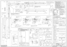
Installation drawing OL 90 N with hand lever
(PDF | 425 KB)